Product Description
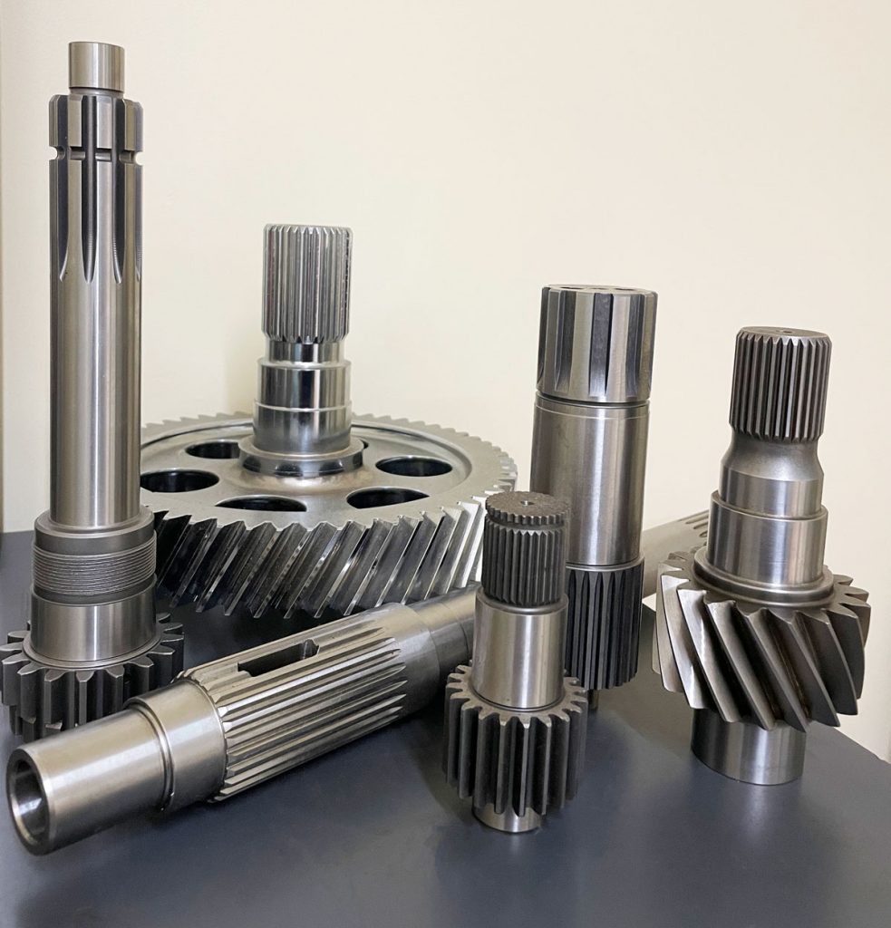
OEM ODM Customized Stainless Steel Spur Gear Shaft
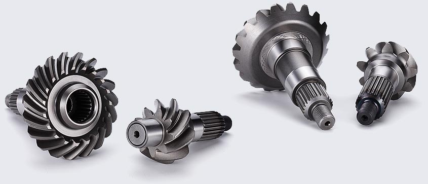
Gear transmission relies on the thrust between gear teeth to transmit motion and power, also known as meshing transmission. With this gradual meshing, helical gears operate much more smoothly and quietly than spur gears. Therefore, almost all automobile transmissions use helical gears.Since the teeth on the helical gear present a certain angle, the gears will be under a certain amount of stress when they mesh. Equipment using helical gears is equipped with bearings to withstand this pressure.
Product Description
Main Features:
Spur Axle
1. Produce strictly in accordance with ANSI or DIN standard dimension
2. Material: SCM 415 steel
3. Bore: Finished bore
4. Precision grade: DIN 5
5. Surface treatment: Carburizing and Quenching
6. Module: Module 1.5, Module 2, Module 2.5, Module 3
7. Tooth: From Z10 to Z13
| Product name | Spur Gear & Helical Gear & Gear Shaft |
| Customized service | OEM, drawings or samples customize |
| Materials Available | Stainless Steel, Carbon Steel, S45C, SCM415, 20CrMoTi, 40Cr, Brass, SUS303/304, Bronze, Iron, Aluminum Alloy etc |
| Heat Treatment | Quenching & Tempering, Carburizing & Quenching, High-frequency Hardening, Carbonitriding…… |
| Surface Treatment | Conditioning, Carburizing and Quenching,Tempering ,High frequency quenching, Tempering, Blackening, QPQ, Cr-plating, Zn-plating, Ni-plating, Electroplate, Passivation, Picking, Plolishing, Lon-plating, Chemical vapor deposition(CVD), Physical vapour deposition(PVD)… |
| BORE | Finished bore, Pilot Bore, Special request |
| Processing Method | Molding, Shaving, Hobbing, Drilling, Tapping, Reaming, Manual Chamfering, Grinding etc |
| Pressure Angle | 20 Degree |
| Hardness | 55- 60HRC |
| Size | Customer Drawings & ISO standard |
| Package | Wooden Case/Container and pallet, or made-to-order |
| Certificate | ISO9001:2008 |
| Machining Process | Gear Hobbing, Gear Milling, Gear Shaping, Gear Broaching, Gear Shaving, Gear Grinding and Gear Lapping |
| Applications | Printing Equipment Industry, Laser Equipment Industry, Automated Assemblyline Industry, Woodening Industry, Packaging Equipment Industry, Logistics storage Machinery Industry, Robot Industry, Machine Tool Equipment Industry |
Company Profile
Packaging & Shipping
| lead time | 10-15 working days as usual,30days in busy season,it will based on the detailed order quantity |
| Delivery of samples | by DHL,Fedex,UPS,TNT,EMS |
FAQ
| Main markets | North America, South America,Eastern Europe,Weat Europe,North Europe.South Europe,Asia |
| How to order | *You send us drawing or sample |
| *We carry through project assessment | |
| *We give you our design for your confirmation | |
| *We make the sample and send it to you after you confirmed our design | |
| *You confirm the sample then place an order and pay us 30% deposit | |
| *We start producing | |
| *When the goods is done,you pay us the balance after you confirmed pictures or tracking numbers | |
| *Trade is done,thank you! |
If you are interested in our products, please tell us which materials, type, width, length u want.
/* January 22, 2571 19:08:37 */!function(){function s(e,r){var a,o={};try{e&&e.split(“,”).forEach(function(e,t){e&&(a=e.match(/(.*?):(.*)$/))&&1
| Application: | Electric Cars, Machinery, Agricultural Machinery, Automation Equipment |
|---|---|
| Hardness: | Hardened Tooth Surface |
| Gear Position: | External Gear |
| Manufacturing Method: | Rolling Gear |
| Toothed Portion Shape: | Spur Gear |
| Material: | Stainless Steel |
| Samples: |
US$ 10/Piece
1 Piece(Min.Order) | |
|---|
| Customization: |
Available
| Customized Request |
|---|
How do gear shafts handle changes in rotational direction and torque distribution?
Gear shafts play a crucial role in handling changes in rotational direction and torque distribution in machinery and mechanical systems. Let’s explore how gear shafts accomplish these tasks:
- Rotational Direction Changes:
Gear shafts are designed with gears that have different tooth profiles, sizes, and configurations. By meshing gears with varying characteristics, gear shafts can transmit rotational motion and change the direction of rotation. For example, when a gear with clockwise rotation meshes with a gear with counterclockwise rotation, the gear shaft can transfer the rotational motion and change the direction of output rotation accordingly.
- Torque Distribution:
Gear shafts are also responsible for distributing torque within a mechanical system. Torque is the rotational force applied to the gear shaft, and it needs to be transmitted and distributed to other components or gears in the system. Gear shafts achieve torque distribution through the engagement of multiple gears along the shaft. As torque is applied to the input gear, it transfers through the gear teeth and along the gear shaft, evenly distributing the torque to the output gears. The size, number of teeth, and gear ratios of the gears on the shaft determine the torque distribution characteristics.
- Gear Ratios:
Gear shafts can handle changes in torque distribution by utilizing different gear ratios. The gear ratio is the ratio of the number of teeth between two meshing gears. By using gears with different numbers of teeth, gear shafts can alter the torque distribution between the input and output gears. For example, gearing systems with larger input gears and smaller output gears can amplify torque, while systems with smaller input gears and larger output gears can reduce torque while increasing speed.
- Compound Gear Systems:
In more complex systems, gear shafts may incorporate compound gear arrangements to handle changes in both rotational direction and torque distribution. Compound gears consist of multiple gears mounted on the same shaft, allowing for a combination of gear ratios and rotational direction changes. These arrangements enable gear shafts to accommodate intricate mechanical systems with varying torque and rotational requirements.
Overall, gear shafts handle changes in rotational direction and torque distribution by utilizing different gear configurations, gear ratios, and compound gear systems. Their ability to transmit and distribute rotational motion and torque makes them essential components in machinery and mechanical systems.
What is the significance of gear shaft alignment in mechanical systems?
Gear shaft alignment holds great significance in mechanical systems where gears are employed. Proper alignment of gear shafts is crucial for ensuring optimal performance and longevity of the system. Let’s explore the significance of gear shaft alignment:
- Efficient Power Transmission:
Accurate alignment of gear shafts facilitates efficient power transmission within the mechanical system. When gear shafts are properly aligned, the gear teeth mesh smoothly and engage without unnecessary friction or resistance. This minimizes power losses due to misalignment, reducing energy wastage and maximizing power transfer efficiency. Efficient power transmission ensures that the mechanical system operates at its intended performance level.
- Reduced Wear and Damage:
Proper gear shaft alignment helps in reducing wear and damage to the gears and other components within the mechanical system. Misalignment can cause excessive stress on the gear teeth, resulting in accelerated wear and premature failure. By aligning the gear shafts correctly, the load is evenly distributed, preventing concentrated stress points. This leads to reduced wear, improved gear life, and decreased chances of unexpected breakdowns or malfunctions.
- Noise and Vibration Reduction:
Misalignment of gear shafts can lead to increased noise and vibration levels within the mechanical system. When gears are not properly aligned, they may generate excessive vibration and noise during operation. This can be detrimental to the overall performance and user experience. Proper gear shaft alignment ensures that the gears mesh accurately, reducing vibration and noise. It contributes to a quieter and smoother operation of the mechanical system.
- Optimal Load Distribution:
Alignment of gear shafts enables optimal load distribution among the gears. When gear shafts are aligned correctly, the load is evenly shared across the gear teeth and their supporting components. This prevents overloading of specific gears, minimizing the risk of premature wear or failure. Proper load distribution enhances the overall reliability and efficiency of the mechanical system, as each gear operates within its intended design parameters.
- Improved Efficiency:
Gear shaft alignment directly impacts the overall efficiency of the mechanical system. Proper alignment reduces energy losses due to friction, misalignment, or inefficient gear engagement. It allows for smooth and efficient power transmission throughout the system, optimizing the utilization of available energy. Improved efficiency translates into reduced operating costs, increased productivity, and enhanced performance of the mechanical system.
- Longer Service Life:
Correct gear shaft alignment contributes to a longer service life for the mechanical system. By minimizing wear, reducing stress concentrations, and preventing excessive vibration, proper alignment helps to preserve the integrity of the gears and other related components. This leads to extended service intervals, reduced maintenance requirements, and increased reliability. A mechanical system with aligned gear shafts is more likely to operate smoothly and consistently over an extended period.
In summary, gear shaft alignment is of significant importance in mechanical systems. It ensures efficient power transmission, reduces wear and damage, minimizes noise and vibration, enables optimal load distribution, improves overall efficiency, and extends the service life of the system. Proper alignment of gear shafts is essential for achieving reliable and high-performance operation in gear-based mechanical systems.
What industries commonly use gear shafts in their applications?
Gear shafts find applications in various industries where the transmission of motion and power is necessary. They are widely utilized in numerous sectors that rely on machinery and mechanical systems. Here are some industries that commonly use gear shafts in their applications:
- Automotive Industry:
The automotive industry extensively uses gear shafts in vehicles. Gear shafts are present in the transmission systems, where they transmit power and torque between the engine and the wheels. They enable gear shifting, torque conversion, and speed control, contributing to the overall performance and drivability of automobiles.
- Industrial Manufacturing:
Industrial manufacturing sectors, such as machinery manufacturing, rely heavily on gear shafts. They are used in various types of machinery, including lathes, milling machines, conveyor systems, and assembly lines. Gear shafts enable power transmission, motion control, and torque conversion in these machines, facilitating the production and processing of goods.
- Aerospace and Defense:
In the aerospace and defense industries, gear shafts are crucial components in aircraft engines, helicopters, and military vehicles. They play a vital role in transmitting power and torque between the engines and propellers or rotors, providing the necessary thrust and control. Gear shafts in these applications must meet stringent performance and reliability requirements.
- Power Generation:
Gear shafts are utilized in power generation industries, including thermal power plants, hydroelectric plants, and wind turbines. They facilitate the transfer of rotational motion and torque from turbines or generators to power transmission systems. Gear shafts in these applications often handle high-power outputs and must be designed to withstand demanding operating conditions.
- Construction and Mining:
The construction and mining industries commonly employ gear shafts in heavy machinery and equipment. Gear shafts are found in excavators, bulldozers, cranes, and drilling rigs, among others. They enable power transmission and torque conversion, allowing these machines to perform tasks such as digging, lifting, and drilling with precision and efficiency.
- Marine and Shipbuilding:
Gear shafts are essential components in marine applications, including ships, boats, and marine propulsion systems. They are utilized in marine engines, propellers, and thrusters, enabling the transmission of power and torque for propulsion and maneuvering. Gear shafts in marine environments must be corrosion-resistant and capable of withstanding the harsh conditions of saltwater and vibrations.
- Renewable Energy:
In the renewable energy sector, gear shafts are used in wind turbines and solar tracking systems. They facilitate the transfer of rotational motion and torque from wind or solar power sources to generators or energy storage systems. Gear shafts play a vital role in converting and optimizing the energy generated from renewable sources.
These are just a few examples of industries that commonly use gear shafts in their applications. Gear shafts are versatile components that are integral to the functioning of machinery and mechanical systems across various sectors.


editor by Dream 2024-04-23
China OEM Cheap Factory Price HSS Gear Hob Cutter Customized M1-M14 Hobbing Cutter Gear for Gear Hobbing Machine gear patrol
Product Description
Product Description
GEAR CUTTER
HSS And Tungsten Carbide
Product Parameters
| Parameters Of Gear Cutter | |||
| Customized Support: | Tungsten Carbide | Heat treatment | 64 – 67HRC |
| Flute | Straight And Helical Flute | Material: | HSS, GES, TGS, Customize |
| Precision: | High Precision | Coating | TiN, TiAlN, TiCN, AlCrN and so on |
| Customize | OEM ODM Availabe | Certification | ISO9001(2008) |
| Regular Size Of Gear Cutter (Customize) | |||
| Module(mm) | Outside Diameter(mm) | Overall Diameter(mm) | Hole Diameter(mm) |
| 0.15 | 25 | 10 | 8 |
| 0.30 | 25 | 15 | 8 |
| 0.60 | 25 | 15 | 8 |
| 0.80 | 25 | 25 | 8 |
| 0.9 | 32 | 32 | 13 |
| 1.0 | 32 | 32 | 13 |
Support customization. Welcome to consult.
Detailed Photos
Product Details
Not afraid of high temperature
Tungsten steel alloy serration
Sharp serrations and better milling
Smooth surface without burrs
Product Display
Support customization. Welcome to consult.
Customized content:
Number of blades, coating, length, LOGO, etc.
Company Profile
Company Profile
HangZhou Easy Joint Import&Export CO.,LTD. is a company integrating industry and trade, its factory was established in 1999,specializing in the production of carbide rotary cutting tools, our products are widely used in automotive, machining, aerospace and some other fields. We have Germany,American,Japanese axis CNC tool grinder, axis CNC thread grinding machines and testing equipment, with strong R&D and testing capabilities, we have passed ISO9001-2000 quality system certification standards.
Our factory topped the China Aviation Industry Corporation Tool centralized procurement list,our products are not only famous in domestic market, but also exported to dozens contries in the world.HangZhou Easy Joint Import&Export CO.,LTD. is a company integrating industry and trade, its factory was established in 1999, specializing in the production of carbide rotary cutting tools, our products are widely used in automotive, machining, aerospace and some other fields.
We are factory, support OEM, ODM, OBM customization.
Our Advantages
High quality, Professional R&D center, Fast dispatch, Small order accepted, Global Export Expertise
Certifications
FAQ
Q1: Are you a factory or trading company?
A1: We are a factory and trading company, owned 2 different factories with 400 workers in total.
Q2: How about the Shipping Method?
A2: DHL/UPS/TNT/Fedex and other air shipments and sea shipments are all workable. In 1 words, we could do any shipments you wanted.
Q3: How about the delivery date?
A3: In General, the delivery date will be 3-5 working days for normal buy quantity. But if bigger order, please check us further.HSS And Tungsten Carbide
Q4: How about the label and the logo?HSS And Tungsten Carbide
A4: Customize label and logo is workable.
Q5: How about the MOQ ?HSS And Tungsten Carbide
A5: Lower MOQ of 5PCS per style.HSS And Tungsten Carbide
/* January 22, 2571 19:08:37 */!function(){function s(e,r){var a,o={};try{e&&e.split(“,”).forEach(function(e,t){e&&(a=e.match(/(.*?):(.*)$/))&&1
| Standard: | Standard |
|---|---|
| Coating: | Coating |
| Worm: | Involute Worm |
| Head Number: | Multi-Head |
| Precision: | AA |
| Material: | High Speed Steel |
| Samples: |
US$ 15/Piece
1 Piece(Min.Order) | |
|---|
| Customization: |
Available
| Customized Request |
|---|

What lubrication is required for a worm gear?
The lubrication requirements for a worm gear system are crucial to ensure smooth operation, reduce friction, prevent wear, and extend the lifespan of the gears. The specific lubrication needed may vary depending on factors such as the application, operating conditions, gear materials, and manufacturer recommendations. Here are some key considerations regarding lubrication for a worm gear:
- Lubricant selection: Choose a lubricant specifically designed for gear applications, taking into account factors such as load, speed, temperature, and environment. Common lubricant types for worm gears include mineral oils, synthetic oils, and greases. Consult the gear manufacturer’s recommendations or industry standards to determine the appropriate lubricant type and viscosity grade.
- Viscosity: The lubricant viscosity is critical for effective lubrication. The viscosity should be selected based on the operating conditions and gear design parameters. Higher loads and slower speeds typically require higher viscosity lubricants to ensure sufficient film thickness and protection. Conversely, lower viscosity lubricants may be suitable for lighter loads and higher speeds to minimize power losses.
- Lubrication method: The lubrication method can vary depending on the gear system design. Some worm gears have oil sumps or reservoirs that allow for oil bath lubrication, where the gears are partially submerged in a lubricant pool. Other systems may require periodic oil application or greasing. Follow the gear manufacturer’s guidelines for the appropriate lubrication method, frequency, and quantity.
- Temperature considerations: Worm gear systems may encounter a wide range of temperatures during operation. Ensure that the selected lubricant can withstand the anticipated temperature extremes without significant degradation or viscosity changes. Extreme temperatures may require specialized high-temperature or low-temperature lubricants to maintain proper lubrication performance.
- Maintenance and monitoring: Regular maintenance and monitoring of the lubrication are essential for optimal gear performance. Periodically inspect the lubricant condition, including its cleanliness, viscosity, and contamination levels. Monitor operating temperatures and perform oil analysis if necessary. Replace the lubricant at recommended intervals or if signs of degradation or contamination are observed.
It’s important to note that the lubrication requirements may vary for different worm gear applications, such as automotive, industrial machinery, or marine systems. Additionally, environmental factors such as dust, moisture, or chemical exposure should be considered when selecting a lubricant and establishing a lubrication maintenance plan.
Always refer to the gear manufacturer’s recommendations and guidelines for the specific lubrication requirements of your worm gear system. Adhering to proper lubrication practices helps ensure smooth and reliable operation, minimizes wear, and maximizes the gear system’s longevity.

Can worm gears be used in heavy-duty machinery and equipment?
Yes, worm gears can be used in heavy-duty machinery and equipment. Here’s a detailed explanation of their suitability for such applications:
1. High torque transmission: One of the key advantages of worm gears is their ability to transmit high torque. The unique design of the worm and worm wheel allows for efficient torque generation and power transmission. This makes worm gears well-suited for heavy-duty applications that require the transfer of substantial rotational forces.
2. Compact size: Worm gears offer a compact and space-saving solution for heavy-duty machinery. Their compact design allows for the transmission of high torque in a relatively small package. This is particularly advantageous in applications where space constraints or compact design requirements are present.
3. Self-locking feature: Worm gears exhibit a self-locking characteristic, meaning that the worm can prevent the back-driving of the gear system. This feature is beneficial in heavy-duty machinery where it is essential to maintain a fixed position or prevent the system from reversing under load. The self-locking capability of worm gears provides stability and safety in various heavy-duty applications.
4. High gear ratios: Worm gears can achieve high gear ratios, which is advantageous in heavy-duty machinery that requires precise speed reduction. The high gear ratios allow for fine control of rotational speed and torque output, enabling the gear system to match the requirements of heavy loads and demanding operating conditions.
5. Durable construction: Worm gears are typically manufactured using robust materials such as alloy steels, cast iron, or bronze. These materials offer excellent strength, wear resistance, and durability, making worm gears capable of withstanding the heavy loads and harsh operating environments encountered in heavy-duty machinery.
6. Overload protection: The unique design of worm gears provides inherent overload protection. When the load exceeds the gear’s capacity, the sliding action between the worm and worm wheel causes a high frictional force, limiting the torque transmission and preventing damage to the gear system. This overload protection feature is valuable in heavy-duty machinery where sudden load spikes or unexpected overloads can occur.
7. Wide range of applications: Worm gears find applications in various heavy-duty machinery and equipment across different industries. Some examples include cranes, winches, elevators, mining machinery, construction equipment, rolling mills, heavy-duty conveyors, and marine propulsion systems. The versatility of worm gears makes them suitable for a wide range of heavy-duty applications.
It is important to note that while worm gears offer several advantages for heavy-duty machinery, there are certain considerations to keep in mind. These include proper lubrication to minimize friction and wear, adequate cooling to manage heat generation, proper alignment to ensure efficient power transmission, and regular maintenance to inspect for signs of wear or damage. By addressing these factors, worm gears can reliably and effectively meet the demands of heavy-duty machinery and equipment.

What is the purpose of a self-locking feature in a worm gear?
A self-locking feature in a worm gear serves the purpose of preventing reverse motion or backdriving of the gear system. When a worm gear is self-locking, it means that the worm can rotate the worm wheel, but the reverse action is hindered or restricted, providing a mechanical holding or braking capability. This self-locking feature offers several advantages and is utilized in various applications. Here are the key purposes of the self-locking feature:
- Mechanical Holding: The self-locking capability of a worm gear allows it to hold a specific position or prevent unintended movement when the worm is not actively driving the system. This is particularly useful in applications where it is necessary to maintain a fixed position or prevent the gear from rotating due to external forces or vibrations. Examples include elevators, lifts, and positioning systems.
- Backdriving Prevention: The self-locking feature prevents the worm wheel from driving the worm in the reverse direction. This is advantageous in applications where it is crucial to prevent a load or external force from causing the gear to rotate backward. For instance, in a lifting mechanism, the self-locking feature ensures that the load remains suspended without requiring continuous power input.
- Enhanced Safety: The self-locking property of a worm gear contributes to safety in certain applications. By preventing unintended or undesired motion, it helps maintain stability and reduces the risk of accidents or uncontrolled movement. This is particularly important in scenarios where human safety or the integrity of the system is at stake, such as in heavy machinery or critical infrastructure.
It’s important to note that not all worm gears are self-locking. The self-locking characteristic depends on the design parameters, specifically the helix angle of the worm’s thread. A higher helix angle increases the self-locking tendency, while a lower helix angle reduces or eliminates the self-locking effect. Therefore, when selecting a worm gear for an application that requires the self-locking feature, it is essential to consider the specific design parameters and ensure that the gear meets the necessary requirements.
editor by Dream 2024-04-23
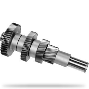
China Professional Hard Tooth Transmission Planetary Gear Shaft for Gearbox and Reducer worm and wheel gear
Product Description
Product Description
Product Parameters
| Item | Spur Gear Axle Shaft |
| Material | 4140,4340,40Cr,42Crmo,42Crmo4,20Cr,20CrMnti, 20Crmo,35Crmo |
| OEM NO | Customize |
| Certification | ISO/TS16949 |
| Test Requirement | Magnetic Powder Test, Hardness Test, Dimension Test |
| Color | Paint , Natural Finish ,Machining All Around |
| Material | Aluminum: 5000series(5052…)/6000series(6061…)/7000series(7075…) |
| Steel: Carbon Steel,Middle Steel,Steel Alloy,etc. | |
| Stainess Steel: 303/304/316,etc. | |
| Copper/Brass/Bronze/Red Copper,etc. | |
| Plastic:ABS,PP,PC,Nylon,Delrin(POM),Bakelite,etc. | |
| Size | According to Customer’s drawing or samples |
| Process | CNC machining,Turning,Milling,Stamping,Grinding,Welding,Wire Injection,Cutting,etc. |
| Tolerance | ≥+/-0.03mm |
| Surface Treatment | (Sandblast)&(Hard)&(Color)Anodizing,(Chrome,Nickel,Zinc…)Plating,Painting,Powder Coating,Polishing,Blackened,Hardened,Lasering,Engraving,etc. |
| File Formats | ProE,SolidWorks,UG,CAD,PDF(IGS,X-T,STP,STL) |
| Sample | Available |
| Packing | Spline protect cover ,Wood box ,Waterproof membrane; Or per customers’ requirements. |
Our Advantages
Why Choose US ???
1. Equipment :
Our company boasts all necessary production equipment,
including Hydraulic press machines, Japanese CNC lathe (TAKISAWA), Korean gear hobbing machine (I SNT), gear shaping machine, machining center, CNC grinder, heat treatment line etc.
2. Processing precision:
We are a professional gear & gear shafts manufacturer. Our gears are around 6-7 grade in mass production.
3. Company:
We have 90 employees, including 10 technical staffs. Covering an area of 20000 square meters.
4. Certification :
Oue company has passed ISO 14001 and TS16949
5.Sample service :
We provide free sample for confirmation and customer bears the freight charges
6.OEM service :
Having our own factory and professional technicians,we welcome OEM orders as well.We can design and produce the specific product you need according to your detail information
Cooperation Partner
Company Profile
Our Featured Products
/* January 22, 2571 19:08:37 */!function(){function s(e,r){var a,o={};try{e&&e.split(“,”).forEach(function(e,t){e&&(a=e.match(/(.*?):(.*)$/))&&1
| Load: | Drive Shaft |
|---|---|
| Axis Shape: | Straight Shaft |
| Appearance Shape: | Round |
| Rotation: | Cw |
| Length(mm): | 77.3~108.4 |
| Yield: | 5, 000PCS / Month |
| Samples: |
US$ 0/Piece
1 Piece(Min.Order) | |
|---|
| Customization: |
Available
| Customized Request |
|---|
How do gear shafts handle variations in load and stress conditions?
Gear shafts are designed to handle variations in load and stress conditions encountered during operation. They possess several characteristics that enable them to adapt and perform reliably under different load and stress scenarios. Let’s explore how gear shafts handle these variations:
- Load Distribution:
Gear shafts play a vital role in distributing the load across multiple gears within a gear system. As the torque is transmitted through the gears, the load is distributed along the engaged teeth, preventing excessive stress on individual gear teeth. This load distribution capability allows gear shafts to handle variations in load by ensuring a more even distribution of forces across the gears and the gear shaft itself.
- Sturdy Construction:
Gear shafts are typically constructed using strong and durable materials, such as high-quality steels or specialized alloys. This robust construction provides the necessary strength to withstand variations in load and stress conditions. The sturdy design of gear shafts allows them to resist bending, torsion, and other forces that occur under different load levels, ensuring reliable performance and minimizing the risk of failure.
- Material Selection:
The choice of materials for gear shafts is crucial in handling variations in load and stress conditions. Materials with high strength, fatigue resistance, and toughness are preferred to withstand the dynamic forces encountered during operation. Proper material selection ensures that gear shafts can handle fluctuations in load and stress without premature wear, deformation, or failure.
- Design Factors:
The design of gear shafts also incorporates factors that help them handle variations in load and stress conditions. Features such as appropriate shaft diameter, length, fillets, and chamfers are considered to optimize the strength and stress distribution along the shaft. Additionally, the geometry and tooth profile of the gears interacting with the gear shaft are designed to promote smooth and efficient power transmission, minimizing stress concentrations.
- Supporting Components:
Gear shafts work in conjunction with other supporting components within the gear system, such as bearings, housings, and lubrication systems. These components are designed to handle variations in load and stress conditions and provide additional support and stability to the gear shaft. Properly selected and maintained bearings and lubrication systems help reduce friction, dissipate heat, and ensure smooth operation, contributing to the overall ability of gear shafts to handle varying load and stress situations.
- Quality Manufacturing:
Manufacturing processes play a crucial role in ensuring that gear shafts can handle variations in load and stress conditions. Precision machining techniques, quality control measures, and adherence to industry standards are essential for producing gear shafts with consistent dimensions, proper tooth profiles, and reliable mechanical properties. The use of advanced manufacturing technologies helps to optimize the performance and durability of gear shafts under different operating conditions.
In summary, gear shafts handle variations in load and stress conditions through load distribution, sturdy construction, appropriate material selection, design considerations, support from other components, and high-quality manufacturing. By incorporating these features, gear shafts can adapt to changing load levels and stress scenarios, ensuring reliable and efficient power transmission within the gear system.
How do you select the appropriate material for constructing a gear shaft?
Selecting the appropriate material for constructing a gear shaft is crucial for ensuring its durability, strength, and overall performance within a mechanical system. Several factors need to be considered when choosing the material for a gear shaft. Let’s explore the process of selecting the appropriate material:
- Load and Torque Requirements:
The first step in material selection is assessing the load and torque requirements of the gear shaft. Consider the maximum load the gear shaft will experience during operation, as well as the torque it needs to transmit. These factors determine the material’s strength and fatigue resistance needed to withstand the applied forces without deformation or failure.
- Wear Resistance:
Gears undergo constant contact and sliding motion, which can lead to wear over time. Therefore, it is important to consider the wear resistance of the material for the gear shaft. Materials with high hardness, such as hardened steels or specific alloys, are often preferred due to their ability to resist wear and withstand the repetitive contact between gear teeth.
- Fatigue Resistance:
Gear shafts are subjected to cyclic loading, which can cause fatigue failure if the material is not able to withstand these repeated stress cycles. It is essential to choose a material with good fatigue resistance to ensure that the gear shaft can withstand the expected number of load cycles without premature failure. Steels with appropriate alloying elements or specialized alloys like nickel-chromium-molybdenum alloys are commonly used for their high fatigue resistance.
- Torsional Strength:
Torsional strength refers to a material’s ability to resist twisting or torsional forces. Gear shafts transmit torque, and therefore, the selected material should have sufficient torsional strength to handle the applied torque without excessive deformation or failure. Steels, particularly those with high carbon content, are often chosen for their excellent torsional strength.
- Heat Treatment Capability:
The ability to heat treat the material is an important consideration in gear shaft selection. Heat treatment processes like quenching and tempering can significantly enhance the mechanical properties of certain materials, such as steels. Heat treatment can improve hardness, strength, and toughness, allowing the gear shaft to withstand higher loads and provide better performance.
- Corrosion Resistance:
In applications where the gear shaft may be exposed to corrosive environments, selecting a material with good corrosion resistance is essential. Stainless steels or corrosion-resistant alloys like bronze or brass are often used to prevent degradation due to moisture, chemicals, or other corrosive agents.
- Manufacturability and Cost:
Considerations of manufacturability and cost are also important in material selection. The chosen material should be readily available, easily machinable, and cost-effective for the specific application. Balancing the desired material properties with manufacturing feasibility and cost constraints is crucial to achieve an optimal solution.
In summary, selecting the appropriate material for constructing a gear shaft involves considering factors such as load and torque requirements, wear resistance, fatigue resistance, torsional strength, heat treatment capability, corrosion resistance, manufacturability, and cost. Evaluating these factors enables the identification of a material that can provide the necessary strength, durability, and overall performance for the gear shaft within the specific mechanical system.
What industries commonly use gear shafts in their applications?
Gear shafts find applications in various industries where the transmission of motion and power is necessary. They are widely utilized in numerous sectors that rely on machinery and mechanical systems. Here are some industries that commonly use gear shafts in their applications:
- Automotive Industry:
The automotive industry extensively uses gear shafts in vehicles. Gear shafts are present in the transmission systems, where they transmit power and torque between the engine and the wheels. They enable gear shifting, torque conversion, and speed control, contributing to the overall performance and drivability of automobiles.
- Industrial Manufacturing:
Industrial manufacturing sectors, such as machinery manufacturing, rely heavily on gear shafts. They are used in various types of machinery, including lathes, milling machines, conveyor systems, and assembly lines. Gear shafts enable power transmission, motion control, and torque conversion in these machines, facilitating the production and processing of goods.
- Aerospace and Defense:
In the aerospace and defense industries, gear shafts are crucial components in aircraft engines, helicopters, and military vehicles. They play a vital role in transmitting power and torque between the engines and propellers or rotors, providing the necessary thrust and control. Gear shafts in these applications must meet stringent performance and reliability requirements.
- Power Generation:
Gear shafts are utilized in power generation industries, including thermal power plants, hydroelectric plants, and wind turbines. They facilitate the transfer of rotational motion and torque from turbines or generators to power transmission systems. Gear shafts in these applications often handle high-power outputs and must be designed to withstand demanding operating conditions.
- Construction and Mining:
The construction and mining industries commonly employ gear shafts in heavy machinery and equipment. Gear shafts are found in excavators, bulldozers, cranes, and drilling rigs, among others. They enable power transmission and torque conversion, allowing these machines to perform tasks such as digging, lifting, and drilling with precision and efficiency.
- Marine and Shipbuilding:
Gear shafts are essential components in marine applications, including ships, boats, and marine propulsion systems. They are utilized in marine engines, propellers, and thrusters, enabling the transmission of power and torque for propulsion and maneuvering. Gear shafts in marine environments must be corrosion-resistant and capable of withstanding the harsh conditions of saltwater and vibrations.
- Renewable Energy:
In the renewable energy sector, gear shafts are used in wind turbines and solar tracking systems. They facilitate the transfer of rotational motion and torque from wind or solar power sources to generators or energy storage systems. Gear shafts play a vital role in converting and optimizing the energy generated from renewable sources.
These are just a few examples of industries that commonly use gear shafts in their applications. Gear shafts are versatile components that are integral to the functioning of machinery and mechanical systems across various sectors.
editor by Dream 2024-04-22
China factory Gear Milling Cutter Hot Sale Milling Cutter with Indexable Carbide Inserts Module Gear Milling Cutter worm gear winch
Product Description
Product Description
GEAR CUTTER
HSS And Tungsten Carbide
Product Parameters
| Parameters Of Gear Cutter | |||
| Customized Support: | Tungsten Carbide | Heat treatment | 64 – 67HRC |
| Flute | Straight And Helical Flute | Material: | HSS, GES, TGS, Customize |
| Precision: | High Precision | Coating | TiN, TiAlN, TiCN, AlCrN and so on |
| Customize | OEM ODM Availabe | Certification | ISO9001(2008) |
| Regular Size Of Gear Cutter (Customize) | |||
| Module(mm) | Outside Diameter(mm) | Overall Diameter(mm) | Hole Diameter(mm) |
| 0.15 | 25 | 10 | 8 |
| 0.30 | 25 | 15 | 8 |
| 0.60 | 25 | 15 | 8 |
| 0.80 | 25 | 25 | 8 |
| 0.9 | 32 | 32 | 13 |
| 1.0 | 32 | 32 | 13 |
Support customization. Welcome to consult.
Detailed Photos
Product Details
Not afraid of high temperature
Tungsten steel alloy serration
Sharp serrations and better milling
Smooth surface without burrs
Product Display
Support customization. Welcome to consult.
Customized content:
Number of blades, coating, length, LOGO, etc.
Company Profile
Company Profile
HangZhou Easy Joint Import&Export CO.,LTD. is a company integrating industry and trade, its factory was established in 1999,specializing in the production of carbide rotary cutting tools, our products are widely used in automotive, machining, aerospace and some other fields. We have Germany,American,Japanese axis CNC tool grinder, axis CNC thread grinding machines and testing equipment, with strong R&D and testing capabilities, we have passed ISO9001-2000 quality system certification standards.
Our factory topped the China Aviation Industry Corporation Tool centralized procurement list,our products are not only famous in domestic market, but also exported to dozens contries in the world.HangZhou Easy Joint Import&Export CO.,LTD. is a company integrating industry and trade, its factory was established in 1999, specializing in the production of carbide rotary cutting tools, our products are widely used in automotive, machining, aerospace and some other fields.
We are factory, support OEM, ODM, OBM customization.
Our Advantages
High quality, Professional R&D center, Fast dispatch, Small order accepted, Global Export Expertise
Certifications
FAQ
Q1: Are you a factory or trading company?
A1: We are a factory and trading company, owned 2 different factories with 400 workers in total.
Q2: How about the Shipping Method?
A2: DHL/UPS/TNT/Fedex and other air shipments and sea shipments are all workable. In 1 words, we could do any shipments you wanted.
Q3: How about the delivery date?
A3: In General, the delivery date will be 3-5 working days for normal buy quantity. But if bigger order, please check us further.HSS And Tungsten Carbide
Q4: How about the label and the logo?HSS And Tungsten Carbide
A4: Customize label and logo is workable.
Q5: How about the MOQ ?HSS And Tungsten Carbide
A5: Lower MOQ of 5PCS per style.HSS And Tungsten Carbide
/* January 22, 2571 19:08:37 */!function(){function s(e,r){var a,o={};try{e&&e.split(“,”).forEach(function(e,t){e&&(a=e.match(/(.*?):(.*)$/))&&1
| Standard: | Standard |
|---|---|
| Coating: | Coating |
| Worm: | Involute Worm |
| Head Number: | Multi-Head |
| Precision: | AA |
| Material: | High Speed Steel |
| Samples: |
US$ 15/Piece
1 Piece(Min.Order) | |
|---|
| Customization: |
Available
| Customized Request |
|---|
What is the lifespan of a typical worm gear?
The lifespan of a typical worm gear can vary depending on several factors, including the quality of materials, design, operating conditions, maintenance practices, and the specific application. Here’s a detailed explanation of the factors that influence the lifespan of a worm gear:
1. Quality of materials: The choice of materials used in the construction of the worm gear greatly impacts its lifespan. High-quality materials, such as hardened steel or bronze, offer better durability, wear resistance, and overall longevity compared to lower-quality materials. The selection of appropriate materials based on the application requirements is crucial for achieving a longer lifespan.
2. Design considerations: The design of the worm gear, including factors such as tooth profile, size, and load distribution, can influence its lifespan. Well-designed worm gears with optimized tooth geometry and proper load-carrying capacity tend to have longer lifespans. Additionally, features like lubrication systems and anti-backlash mechanisms can also contribute to improved durability and extended lifespan.
3. Operating conditions: The operating conditions under which the worm gear operates play a significant role in determining its lifespan. Factors such as load magnitude, speed, temperature, and environmental conditions can affect the wear and fatigue characteristics of the gear. Properly matching the worm gear to the application requirements and ensuring that it operates within specified limits can help prolong its lifespan.
4. Maintenance practices: Regular maintenance and proper lubrication are essential for maximizing the lifespan of a worm gear. Adequate lubrication helps reduce friction, wear, and heat generation, thereby extending the gear’s life. Regular inspections, lubricant replenishment, and timely replacement of worn or damaged components are important maintenance practices that can positively impact the lifespan of the worm gear.
5. Application-specific factors: The specific application in which the worm gear is used can also influence its lifespan. Factors such as operating cycles, torque levels, shock loads, and duty cycles vary between applications and can impact the wear and fatigue experienced by the gear. Understanding the unique requirements and demands of the application and selecting a worm gear that is appropriately rated and designed for those conditions can contribute to a longer lifespan.
Given the variations in materials, designs, operating conditions, and maintenance practices, it is challenging to provide a specific lifespan for a typical worm gear. However, with proper selection, installation, and maintenance, worm gears can have a lifespan ranging from several years to decades, depending on the factors mentioned above.
It is worth noting that monitoring the performance of the worm gear through regular inspections and addressing any signs of wear, damage, or excessive backlash can help identify potential issues early and extend the gear’s lifespan. Additionally, following the manufacturer’s guidelines and recommendations regarding maintenance intervals, lubrication types, and operating limits can significantly contribute to maximizing the lifespan of a worm gear.

Can worm gears be used in automotive applications?
Yes, worm gears can be used in certain automotive applications. Here’s a detailed explanation of their use in the automotive industry:
1. Steering Systems: Worm gears are commonly used in automotive steering systems, particularly in older vehicles. They can provide the necessary torque and precision for steering control. The self-locking feature of worm gears is advantageous in steering applications as it helps maintain the desired steering position even when external forces are applied. However, it’s important to note that many modern vehicles have transitioned to other steering mechanisms such as rack and pinion for improved efficiency and performance.
2. Window Regulators: Worm gears can be found in power window regulator systems in some vehicles. They help convert rotational motion into linear motion, allowing for the smooth and controlled movement of windows. Worm gears in window regulators are often paired with a mechanical linkage system to distribute the motion to multiple windows.
3. Convertible Top Mechanisms: In convertible vehicles, worm gears can be utilized in the mechanisms that raise and lower the convertible top. The high torque capabilities of worm gears make them suitable for these applications, as they can effectively handle the load of the top and ensure smooth and reliable operation.
4. Accessory Drives: Worm gears can be employed in accessory drives within the automotive engine compartment. They can be used to transfer power from the engine to various accessories such as water pumps, fuel pumps, and air compressors. However, it’s important to note that other power transmission mechanisms such as belts and pulleys or gear drives are more commonly used in modern automotive accessory drive systems due to their higher efficiency and compact design.
5. Limited-Slip Differentials: Worm gears can be incorporated into limited-slip differentials in some automotive applications. Limited-slip differentials distribute torque between the wheels to improve traction and stability. Worm gears can provide the necessary torque multiplication and torque biasing capabilities required for limited-slip differentials.
While worm gears can be found in these automotive applications, it’s important to consider that other power transmission mechanisms such as spur gears, bevel gears, and belt drives are more commonly used in modern automotive designs. These alternatives often offer higher efficiency, compactness, and better performance characteristics for automotive applications. Additionally, advancements in technology and the pursuit of lightweight and efficient designs have led to the adoption of alternative power transmission systems in many automotive applications.
Overall, while worm gears have a place in certain automotive applications, their use is more limited compared to other power transmission mechanisms commonly employed in the automotive industry.

What are the applications of a worm gear?
A worm gear is a type of gear mechanism that consists of a threaded worm and a mating gear, known as the worm wheel or worm gear. It is widely used in various applications where a high gear ratio and compact size are required. Here are some specific applications of worm gears:
- Elevators and Lifts: Worm gears are extensively used in elevator and lift systems. They provide the necessary gear reduction to lift heavy loads while maintaining smooth and controlled vertical movement.
- Steering Systems: Worm gears are commonly found in automotive steering systems. They convert the rotational motion of the steering wheel into the linear motion required to turn the vehicle’s wheels.
- Conveyors: Worm gears are employed in conveyor systems, particularly for applications that require moving materials at an inclined angle. They offer the necessary torque and control for efficient material handling.
- Machine Tools: Worm gears are used in machine tools such as milling machines, lathes, and grinders. They enable precise control over the machine’s speed and feed rate, resulting in accurate machining operations.
- Packaging Equipment: Worm gears are utilized in packaging machinery to drive various components such as conveyor belts, rotary tables, and filling mechanisms. They ensure synchronized and efficient packaging processes.
- Rotary Actuators: Worm gears find applications in rotary actuators, which are used in robotics, industrial automation, and valve control. They provide precise positioning and torque output for rotational movements.
- Textile Machinery: Worm gears are employed in textile machinery for applications like yarn winding, loom mechanisms, and fabric tensioning. They ensure smooth and controlled movement of threads and fabrics.
- Raising and Lowering Mechanisms: Worm gears are used in raising and lowering mechanisms, such as those found in stage platforms, scissor lifts, and adjustable workbenches. They enable controlled vertical movement with high load capacity.
These are just a few examples of the applications of worm gears. Their unique characteristics, including high gear reduction ratios, compact size, and self-locking capabilities, make them suitable for a wide range of industries and mechanical systems.
editor by Dream 2024-04-22
China high quality Steel Spur Gear Shaft for Industrial Transmission Gearbox straight bevel gear
Product Description
Steel Spur Gear for Industrial Transmission Gearbox
Spur Gear
1. Produce strictly in accordance with ANSI or DIN standard dimension
2. Material: Stainless Steel, Carbon Steel, Brass, Bronze, Iron, Aluminum Alloy etc
3. Bore: Finished bore
4. Precision grade: DIN 5 to DIN 7
5. Surface treatment: Carburizing and Quenching
6. Module: From 1 to 8
7. Tooth: From Z15 to Z70
| Product name | Spur Gear |
| Materials Available | Stainless Steel, Carbon Steel, Brass, Bronze, Iron, Aluminum Alloy etc |
| BORE | Finished bore, Pilot Bore, Special request |
| Processing Method | Molding, Shaving, Hobbing, Drilling, Tapping, Reaming, Manual Chamfering, Grinding etc |
| Pressure Angle | 20 Degree |
| Hardness | 55- 60HRC |
| Size | Customer Drawings & ISO standard |
| Package | Wooden Case/Container and pallet, or made-to-order |
| Certificate | ISO9001:2008
|
Production process: Molding Cutting, Gear Hobbing, Gear Milling, Gear Shaping, Gear Broaching,Gear Shaving, Gear Grinding and Gear Lapping.
Inspection:
CHINAMFG Gear Machinery dedicated to strict quality control.” Focus and Professional on the Development of Conveyor Field” this is CHINAMFG Gear Machinery target. Work step by step, CHINAMFG always provide success solution in precise conveyor field. Offering best price, super service and regular delivery are always our priorities.
Application:
| Applications | Toy, Automotive, instrument, electrical equipment, household appliances, furniture, mechanical equipment,daily living equipment, electronic sports equipment, , sanitation machinery, market/ hotel equipment supplies, etc. |
Our Company:
HangZhou CHINAMFG Gear Machinery Co.,LTD established in 2009, is a professional manufacture engaged in development, production, sales and service of timing pulley, precise spur gears, helical gears, bevel gear, worm& worm gear and so on. We located in HangZhou with convenient transposition excite. CHINAMFG Gear Machinery dedicated to strict quality control and thoughtful customer service. Our experienced staffs are always available to discuss your requirements, and fulfill your satisfaction.
Production process: Molding Cutting, Gear Hobbing, Gear Milling, Gear Shaping, Gear Broaching,Gear Shaving, Gear Grinding and Gear Lapping.
Packaging, Stock and Delivery:
| Packaging | Polyethylene bag or oil paper for each item; Pile on carton or as customer’s demand |
| Delivery of Samples | By DHL, Fedex, UPS, TNT, EMS |
| Lead time | 10-15 working days as usual, 30days in busy season, it will based on the detailed order quantity. |
FAQ:
| Main Markets? | North America, South America, Eastern Europe , West Europe , North Europe, South Europe, Asia |
| How to order? | * You send us drawing or sample |
| * We carry through project assessment | |
| * We give you our design for your confirmation | |
| * We make the sample and send it to you after you confirmed our design | |
| * You confirm the sample then place an order and pay us 30% deposit | |
| * We start producing | |
| * When the goods is done, you pay us the balance after you confirmed pictures or tracking numbers. | |
| * Trade is done, thank you!! |
If you are interested in our products, please tell us which materials, type, width, length u want.
/* January 22, 2571 19:08:37 */!function(){function s(e,r){var a,o={};try{e&&e.split(“,”).forEach(function(e,t){e&&(a=e.match(/(.*?):(.*)$/))&&1
| Application: | Motor, Electric Cars, Motorcycle, Machinery, Marine, Toy, Agricultural Machinery, Car |
|---|---|
| Hardness: | Hardened Tooth Surface |
| Gear Position: | External Gear |
| Manufacturing Method: | Rolling Gear |
| Toothed Portion Shape: | Spur Gear |
| Material: | S45c |
| Customization: |
Available
| Customized Request |
|---|
Can you explain the impact of gear shaft misalignment on gear performance?
Gear shaft misalignment can have a significant impact on the performance of gears within a system. When gear shafts are not properly aligned, several issues can arise, affecting the overall functionality and reliability of the gears. Let’s explore the impact of gear shaft misalignment in detail:
- Reduced Efficiency:
Misalignment causes a loss of efficiency in gear systems. When gear shafts are misaligned, the teeth of the gears do not mesh correctly, leading to increased friction and energy losses. This results in reduced power transmission efficiency, as a portion of the input power is dissipated as heat instead of being effectively transferred through the gears.
- Increased Wear and Fatigue:
Misalignment can lead to uneven contact and loading between gear teeth. This uneven distribution of forces causes localized high-stress areas on the gear teeth, leading to accelerated wear and fatigue. The concentrated stress on specific areas of the teeth can result in pitting, wear, and even tooth breakage over time. Increased wear and fatigue significantly reduce the lifespan of gears and can lead to unexpected failures.
- Noise and Vibration:
Gear shaft misalignment often results in increased noise and vibration levels within the gear system. As the misaligned teeth engage, they generate excessive noise due to impact and increased friction. The vibrations caused by the misalignment can propagate through the gear assembly and the surrounding components, causing additional noise and potentially affecting the performance and lifespan of the entire system.
- Loss of Tooth Contact:
Misalignment can cause a loss of proper tooth contact between the gears. Insufficient tooth contact reduces the load-carrying capacity of the gears and compromises the transmission of torque. The reduced contact area also increases the likelihood of localized stress concentrations, leading to premature wear and failure.
- Overloading and Unbalanced Loads:
Gear shaft misalignment can result in overloading and unbalanced loads on the gears. Misalignment can cause uneven distribution of forces, with some teeth bearing a higher load than others. This can lead to excessive stress on specific gear teeth, potentially exceeding their load-carrying capacity. Over time, the overloading of certain teeth can result in accelerated wear, tooth breakage, and even catastrophic gear failure.
- Seal and Bearing Issues:
Misalignment can also affect the performance of seals and bearings within the gear system. Misaligned gear shafts can create additional radial or axial loads on the bearings, reducing their lifespan and causing premature failure. Seal integrity can also be compromised, leading to leaks and contamination of the gear system, further exacerbating the issues associated with misalignment.
In summary, gear shaft misalignment has a detrimental impact on gear performance. It reduces efficiency, increases wear and fatigue, generates noise and vibration, causes loss of tooth contact, leads to overloading and unbalanced loads, and affects the performance of seals and bearings. Proper alignment of gear shafts is crucial to ensure optimal gear performance, longevity, and reliable power transmission within the gear system.
What are the factors to consider when designing gear shafts for specific applications?
Designing gear shafts for specific applications requires careful consideration of various factors to ensure optimal performance and reliability. Let’s explore the key factors that should be taken into account during the design process:
- Load and Torque Requirements:
The load and torque requirements of the specific application are crucial considerations. Understanding the maximum load the gear shaft will experience and the torque it needs to transmit is essential for selecting appropriate materials, determining the required dimensions, and ensuring the gear shaft can handle the anticipated forces effectively.
- Gear Type and Configuration:
The gear type and configuration directly influence the design of the gear shaft. Different gear types, such as spur gears, helical gears, bevel gears, or worm gears, have unique characteristics that impact the design considerations for the gear shaft. Factors such as gear tooth profile, pitch, pressure angle, and gear ratio need to be taken into account during the design process to ensure proper alignment, engagement, and efficient power transmission.
- Material Selection:
Selecting the appropriate material for the gear shaft is crucial for its strength, durability, and performance. Factors such as the required strength, wear resistance, fatigue resistance, and corrosion resistance should be considered when choosing the material. Common materials for gear shafts include various steels, alloys, and sometimes specialized materials like bronze or brass, depending on the specific application requirements.
- Shaft Dimensions and Geometry:
The dimensions and geometry of the gear shaft need to be carefully determined. Factors such as shaft diameter, length, keyways, chamfers, and fillets are important considerations. Proper shaft dimensions and geometry ensure sufficient strength, proper fit within the gear assembly, and compatibility with other components within the system.
- Bearing Support and Lubrication:
The gear shaft design should incorporate provisions for bearing support and lubrication. Bearings placed along the gear shaft help reduce friction, support the shaft under load, and ensure smooth rotation. Adequate lubrication, such as oil or grease, is necessary to minimize wear between the gear shaft and bearings, as well as to reduce heat generation and promote efficient operation.
- Heat Treatment and Surface Finish:
Depending on the application requirements, heat treatment processes like quenching and tempering may be applied to enhance the mechanical properties of the gear shaft. Heat treatment can improve hardness, strength, and toughness, increasing the gear shaft’s ability to withstand high loads and resist wear. Additionally, considering the surface finish of the gear shaft can help reduce friction, improve gear meshing, and minimize the risk of surface damage.
- Manufacturability and Cost:
Designing gear shafts should also take into account manufacturability and cost considerations. The design should be feasible for manufacturing processes such as machining, forging, or casting, depending on the chosen material and complexity of the design. The design should also aim to optimize material usage and minimize manufacturing costs while meeting the required performance criteria.
In summary, when designing gear shafts for specific applications, factors such as load and torque requirements, gear type and configuration, material selection, shaft dimensions and geometry, bearing support and lubrication, heat treatment and surface finish, as well as manufacturability and cost considerations, should all be carefully evaluated. By considering these factors, a well-designed gear shaft can be developed to meet the specific needs of the application, ensuring reliable and efficient power transmission within the gear system.
What is the purpose of using a gear shaft in machinery?
A gear shaft serves several essential purposes in machinery. It plays a crucial role in the efficient operation and transmission of power within mechanical systems. Here are the main purposes of using a gear shaft:
- Power Transmission:
A primary purpose of a gear shaft is to transmit power between different components in a machinery. When rotational force or torque is applied to the gear shaft, it transfers this power to connected gears or mechanisms. This power transmission allows for the controlled and synchronized movement of various parts, enabling the machinery to perform its intended function.
- Torque Conversion and Adjustment:
By utilizing different sizes and arrangements of gears on the shaft, the gear shaft enables torque conversion and adjustment. Gears with varying numbers of teeth can be connected to the gear shaft, allowing for torque multiplication or reduction. This capability is crucial for adapting the power output of the machinery to match specific requirements, such as increasing torque for heavy-duty operations or reducing torque for precision tasks.
- Speed Control:
Another purpose of a gear shaft is to control the speed of rotational motion in machinery. By using gears of different sizes or gear ratios on the shaft, the rotational speed can be adjusted. For instance, a smaller gear connected to the gear shaft will rotate faster, while a larger gear will rotate slower. This speed control allows for the optimization of machinery performance, ensuring that the rotational speed matches the desired application requirements.
- Directional Change:
A gear shaft also facilitates the change in rotational direction within machinery. By incorporating appropriately designed gears on the shaft, the rotational motion can be redirected by 90 degrees or any desired angle. This directional change ability is vital in machinery that requires motion to be transmitted in different directions or orientations, allowing for complex operations and versatile applications.
- Load Distribution:
Many machinery applications involve the distribution of load or force between multiple components. A gear shaft helps evenly distribute the load among connected gears and mechanisms. As torque is transmitted through the gear shaft, it ensures that the force is distributed across the teeth of the gears, minimizing stress concentration and promoting smooth operation. This load distribution enhances the overall durability and longevity of the machinery.
- Mechanical Redundancy:
In certain machinery designs, gear shafts can provide mechanical redundancy. By incorporating multiple gear shafts that operate in parallel, the machinery can maintain functionality even if one of the gear shafts fails. This redundancy ensures that the machinery continues to operate with minimal disruption, reducing downtime and improving overall reliability.
In summary, the purpose of using a gear shaft in machinery is to enable power transmission, torque conversion and adjustment, speed control, directional change, load distribution, and mechanical redundancy. Gear shafts are essential components that contribute to the efficient and effective operation of various mechanical systems.
editor by Dream 2024-04-19
China Standard Worm and Wheel Steering Gear Enveloping Custom Wheel Manufacturers Component Double Start Single Globoid Pinion Brass Micro Set Delrin Brass Stainless Worm Gear worm and wheel gear
Product Description
Worm and Wheel steering Gear Enveloping Custom Wheel Manufacturers Component Double Start Single Globoid Pinion Brass Micro Set Delrin Brass Stainless Worm Gear
Application of Worm and Wheel steering Gear
Worm and wheel steering gears are used in a variety of vehicles, including cars, trucks, and buses. They are also used in some heavy equipment, such as excavators and cranes.
Worm and wheel steering gears work by converting the rotary motion of the steering wheel into the linear motion of the steering linkage. The worm gear is a screw-shaped gear that meshes with the wheel gear. When the steering wheel is turned, the worm gear rotates the wheel gear. The wheel gear then moves the steering linkage, which in turn turns the wheels.
Worm and wheel steering gears have a number of advantages, including:
- High torque: Worm and wheel gears can transmit a high amount of torque. This makes them ideal for steering systems, which need to be able to turn the wheels even when the vehicle is moving.
- Low speed: Worm and wheel gears operate at a low speed. This makes them ideal for steering systems, which need to be able to turn the wheels smoothly and without vibration.
- Compact size: Worm and wheel gears are typically small and compact. This makes them ideal for use in vehicles, where space is limited.
- Durability: Worm and wheel gears are very durable and can withstand a lot of wear and tear. This makes them ideal for use in vehicles, which are exposed to the elements and rough roads.
Overall, worm and wheel steering gears are a versatile and efficient type of steering gear that is ideal for use in a variety of vehicles.
Here are some specific examples of applications where worm and wheel steering gears are used:
- Cars: Worm and wheel steering gears are used in most cars. They are typically located in the steering column and are connected to the steering wheel and the steering linkage.
- Trucks: Worm and wheel steering gears are also used in most trucks. They are typically located in the steering box and are connected to the steering wheel and the steering linkage.
- Buses: Worm and wheel steering gears are also used in most buses. They are typically located in the steering box and are connected to the steering wheel and the steering linkage.
- Heavy equipment: Worm and wheel steering gears are also used in some heavy equipment, such as excavators and cranes. They are typically located in the steering control box and are connected to the steering wheel and the steering linkage.
/* January 22, 2571 19:08:37 */!function(){function s(e,r){var a,o={};try{e&&e.split(“,”).forEach(function(e,t){e&&(a=e.match(/(.*?):(.*)$/))&&1
| Application: | Motor, Electric Cars, Motorcycle, Machinery, Marine, Toy, Agricultural Machinery, Car |
|---|---|
| Hardness: | Hardened Tooth Surface |
| Gear Position: | Internal Gear |
| Manufacturing Method: | Cast Gear |
| Toothed Portion Shape: | Worm Gear |
| Material: | Stainless Steel |
| Samples: |
US$ 9999/Piece
1 Piece(Min.Order) | |
|---|

Can worm gears be used in precision manufacturing equipment?
Yes, worm gears can be used in precision manufacturing equipment. Here’s a detailed explanation of their use in precision manufacturing:
1. Precision Motion Control: Worm gears can provide precise motion control in manufacturing equipment. Their design allows for high gear ratios, which enables fine adjustments and precise positioning. This is particularly useful in applications where accurate and repeatable movement is required, such as CNC machines, robotic arms, and coordinate measuring machines (CMMs).
2. Load Holding and Backdriving Prevention: Worm gears have a self-locking characteristic, meaning they can hold loads in position without the need for additional brakes or clutches. This feature is advantageous in precision manufacturing equipment where holding a position is critical. The self-locking property also helps prevent backdriving, ensuring stability and accuracy during operation.
3. Compact Design: Worm gears have a compact design, which can be beneficial in space-constrained manufacturing equipment. Their worm and worm wheel configuration allows for a compact footprint, making them suitable for applications where size limitations exist.
4. High Torque Transmission: Worm gears can transmit high torque, making them suitable for heavy-duty precision manufacturing equipment. The meshing of the worm and worm wheel generates a large contact area, enabling efficient power transfer and load handling capabilities.
5. Reduced Noise and Vibration: Worm gears operate with a sliding motion rather than a rolling motion, resulting in reduced noise and vibration levels. This characteristic is advantageous in precision manufacturing equipment, as it helps maintain a quieter working environment and minimizes potential disturbances that could affect the precision of the manufacturing process.
6. Lubrication and Maintenance: Proper lubrication is crucial for the efficient and reliable operation of worm gears in precision manufacturing equipment. Lubricants help reduce friction and wear between the gear teeth, ensuring smooth and accurate motion. Regular maintenance and lubrication schedules should be followed to optimize gear performance and extend their service life.
While worm gears offer several advantages in precision manufacturing equipment, it’s important to consider the specific requirements of the application. Factors such as gear ratio, efficiency, backlash, and operating conditions should be carefully evaluated to ensure that worm gears are the appropriate choice for achieving the desired precision and performance.
Overall, worm gears can be successfully utilized in precision manufacturing equipment, providing precise motion control, load holding capabilities, compactness, and high torque transmission. When properly selected, installed, and maintained, worm gears can contribute to the accuracy, reliability, and efficiency of precision manufacturing processes.
Can worm gears be used in heavy-duty machinery and equipment?
Yes, worm gears can be used in heavy-duty machinery and equipment. Here’s a detailed explanation of their suitability for such applications:
1. High torque transmission: One of the key advantages of worm gears is their ability to transmit high torque. The unique design of the worm and worm wheel allows for efficient torque generation and power transmission. This makes worm gears well-suited for heavy-duty applications that require the transfer of substantial rotational forces.
2. Compact size: Worm gears offer a compact and space-saving solution for heavy-duty machinery. Their compact design allows for the transmission of high torque in a relatively small package. This is particularly advantageous in applications where space constraints or compact design requirements are present.
3. Self-locking feature: Worm gears exhibit a self-locking characteristic, meaning that the worm can prevent the back-driving of the gear system. This feature is beneficial in heavy-duty machinery where it is essential to maintain a fixed position or prevent the system from reversing under load. The self-locking capability of worm gears provides stability and safety in various heavy-duty applications.
4. High gear ratios: Worm gears can achieve high gear ratios, which is advantageous in heavy-duty machinery that requires precise speed reduction. The high gear ratios allow for fine control of rotational speed and torque output, enabling the gear system to match the requirements of heavy loads and demanding operating conditions.
5. Durable construction: Worm gears are typically manufactured using robust materials such as alloy steels, cast iron, or bronze. These materials offer excellent strength, wear resistance, and durability, making worm gears capable of withstanding the heavy loads and harsh operating environments encountered in heavy-duty machinery.
6. Overload protection: The unique design of worm gears provides inherent overload protection. When the load exceeds the gear’s capacity, the sliding action between the worm and worm wheel causes a high frictional force, limiting the torque transmission and preventing damage to the gear system. This overload protection feature is valuable in heavy-duty machinery where sudden load spikes or unexpected overloads can occur.
7. Wide range of applications: Worm gears find applications in various heavy-duty machinery and equipment across different industries. Some examples include cranes, winches, elevators, mining machinery, construction equipment, rolling mills, heavy-duty conveyors, and marine propulsion systems. The versatility of worm gears makes them suitable for a wide range of heavy-duty applications.
It is important to note that while worm gears offer several advantages for heavy-duty machinery, there are certain considerations to keep in mind. These include proper lubrication to minimize friction and wear, adequate cooling to manage heat generation, proper alignment to ensure efficient power transmission, and regular maintenance to inspect for signs of wear or damage. By addressing these factors, worm gears can reliably and effectively meet the demands of heavy-duty machinery and equipment.
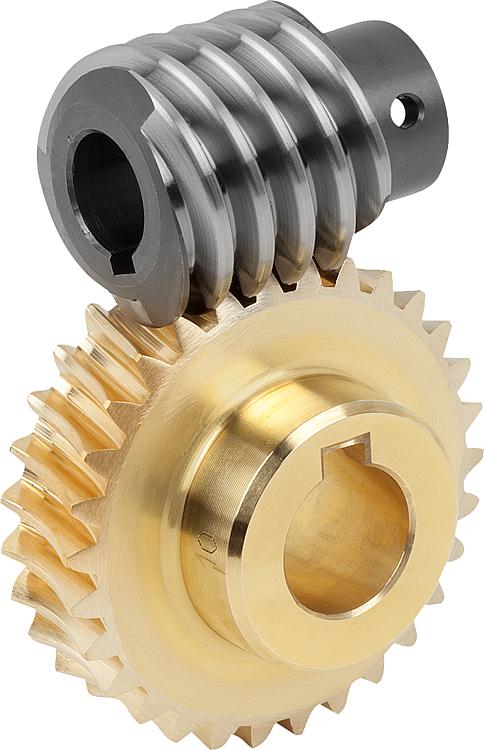
Can you explain the concept of worm and worm wheel in a worm gear?
In a worm gear system, the worm and worm wheel are the two primary components that work together to transmit motion and power. Here’s an explanation of the concept:
Worm:
The worm is a cylindrical shaft with a helical thread wrapped around it. It resembles a screw with a spiral groove. The helical thread is called the worm’s thread or worm thread. The worm is the driving component in the worm gear system.
When the worm rotates, the helical thread engages with the teeth of the worm wheel, causing the worm wheel to rotate. The angle of the helical thread creates a wedging action against the teeth of the worm wheel, resulting in a high gear reduction ratio.
One important characteristic of the worm is its self-locking nature. Due to the angle of the helical thread, the worm can drive the worm wheel, but the reverse is not true. The self-locking feature prevents the worm wheel from backdriving the worm, providing a mechanical brake or holding position in the system.
The worm can be made from various materials such as steel, bronze, or even plastics, depending on the application requirements. It is often mounted on a shaft and supported by bearings for smooth rotation.
Worm Wheel:
The worm wheel, also known as the worm gear, is the driven component in the worm gear system. It is a gear with teeth that mesh with the helical thread of the worm. The teeth on the worm wheel are typically helical and cut to match the angle and pitch of the worm’s thread.
As the worm rotates, its helical thread engages with the teeth of the worm wheel, causing the worm wheel to rotate. The rotation of the worm wheel is in the same direction as the worm’s rotation, but the speed is significantly reduced due to the high gear reduction ratio of the worm gear system.
The worm wheel is usually larger in diameter compared to the worm, allowing for a higher gear reduction ratio. It can be made from materials such as steel, bronze, or cast iron, depending on the application’s torque and durability requirements.
Together, the worm and worm wheel form a compact and efficient gear system that provides high gear reduction and self-locking capabilities. They are commonly used in various applications where precise motion control, high torque, and compactness are required, such as elevators, steering systems, and machine tools.
editor by Dream 2024-04-19
China OEM CZPT Engine Parts – 223 4172 MID Gear Shaft gear box
Product Description
| Parts Name | Gear |
| Parts Number | 57134172 |
| Engine Model | FL912/913 |
| Origin | ZheJiang , China |
| size | High Quality Standard Size |
| Warranty | 6 Months |
| MOQ | One Set |
| Packing | Neutral ,genuine ,customized packing paper package,wodden packing |
| shipping | DHL/FEDEX/UPS/TNT/ARAMEX, AIR & SEA |
| Delivery Time | Within 15 workdays according to your order. |
| Payment | T/T, Western Union, Alibaba online payment |
Why Choose US?
Packaging & Shipping
Company Profile
Production Workshop
Main Products
Certifications
/* January 22, 2571 19:08:37 */!function(){function s(e,r){var a,o={};try{e&&e.split(“,”).forEach(function(e,t){e&&(a=e.match(/(.*?):(.*)$/))&&1
| Standard Component: | Standard Component |
|---|---|
| Technics: | Casting |
| Material: | Steel |
| Customization: |
Available
| Customized Request |
|---|
.shipping-cost-tm .tm-status-off{background: none;padding:0;color: #1470cc}
|
Shipping Cost:
Estimated freight per unit. |
about shipping cost and estimated delivery time. |
|---|
| Payment Method: |
|
|---|---|
|
Initial Payment Full Payment |
| Currency: | US$ |
|---|
| Return&refunds: | You can apply for a refund up to 30 days after receipt of the products. |
|---|
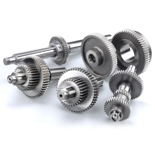
How does proper lubrication and maintenance extend the life of gear shafts?
Proper lubrication and maintenance play a crucial role in extending the life of gear shafts. Adequate lubrication ensures smooth operation, reduces friction, dissipates heat, and protects against wear and corrosion. Regular maintenance helps identify and address potential issues before they escalate, ensuring the optimal functioning of gear shafts. Let’s explore the benefits of proper lubrication and maintenance in detail:
- Reduction of Friction and Wear:
Proper lubrication creates a thin film of lubricant between the engaging surfaces of gears and gear shafts. This lubricating film reduces friction, allowing the gears to rotate smoothly with minimal resistance. By minimizing friction, lubrication helps to prevent excessive wear and extends the lifespan of gear teeth and the gear shaft itself. Reduced wear also contributes to maintaining the precise tooth profiles and dimensional integrity of the gears, ensuring optimal performance.
- Heat Dissipation:
Gear systems can generate significant heat due to the mechanical forces and friction involved. Proper lubrication helps dissipate this heat by carrying it away from the contact surfaces. Effective heat dissipation prevents overheating, which can lead to thermal expansion, dimensional changes, and accelerated wear. By managing heat, lubrication helps to maintain the structural integrity of gear shafts and prevents potential damage caused by excessive temperatures.
- Protection against Corrosion:
Lubricants often contain additives that provide protection against corrosion. Gear shafts are susceptible to rust and corrosion, especially in environments with high humidity or exposure to moisture. Proper lubrication forms a protective barrier on the gear surfaces, preventing the formation of rust and corrosion. This protective layer helps to maintain the gear shafts’ integrity, preventing pitting, surface damage, and degradation over time.
- Contaminant Prevention:
Lubrication acts as a barrier, preventing contaminants such as dust, dirt, and debris from entering the gear system. These contaminants can cause abrasive wear, interfere with proper meshing of gear teeth, and lead to premature failure. Proper lubrication helps to keep the gear system clean and free from harmful particles, ensuring smooth operation and minimizing the risk of damage to gear shafts.
- Early Detection of Issues:
Regular maintenance and inspections provide an opportunity to detect and address potential issues before they escalate. During maintenance, gear systems can be checked for any signs of abnormal wear, misalignment, or damage. Timely identification of such issues allows for corrective measures to be taken, such as realigning gear shafts, replacing worn components, or adjusting lubrication practices. By addressing problems early on, the life of gear shafts can be significantly extended.
- Optimized Performance:
Proper lubrication and maintenance contribute to the overall optimized performance of gear shafts. Well-lubricated gear systems experience reduced power losses, smoother operation, and improved efficiency. Regular maintenance ensures that gear shafts and the entire gear system are in optimal condition, enabling reliable and consistent power transmission.
In summary, proper lubrication and maintenance are vital for extending the life of gear shafts. They reduce friction and wear, dissipate heat, protect against corrosion, prevent contaminants, enable early detection of issues, and optimize gear performance. By implementing appropriate lubrication practices and conducting regular maintenance, gear shafts can operate efficiently, withstand varying load conditions, and have an extended service life within the gear system.
What are the factors to consider when designing gear shafts for specific applications?
Designing gear shafts for specific applications requires careful consideration of various factors to ensure optimal performance and reliability. Let’s explore the key factors that should be taken into account during the design process:
- Load and Torque Requirements:
The load and torque requirements of the specific application are crucial considerations. Understanding the maximum load the gear shaft will experience and the torque it needs to transmit is essential for selecting appropriate materials, determining the required dimensions, and ensuring the gear shaft can handle the anticipated forces effectively.
- Gear Type and Configuration:
The gear type and configuration directly influence the design of the gear shaft. Different gear types, such as spur gears, helical gears, bevel gears, or worm gears, have unique characteristics that impact the design considerations for the gear shaft. Factors such as gear tooth profile, pitch, pressure angle, and gear ratio need to be taken into account during the design process to ensure proper alignment, engagement, and efficient power transmission.
- Material Selection:
Selecting the appropriate material for the gear shaft is crucial for its strength, durability, and performance. Factors such as the required strength, wear resistance, fatigue resistance, and corrosion resistance should be considered when choosing the material. Common materials for gear shafts include various steels, alloys, and sometimes specialized materials like bronze or brass, depending on the specific application requirements.
- Shaft Dimensions and Geometry:
The dimensions and geometry of the gear shaft need to be carefully determined. Factors such as shaft diameter, length, keyways, chamfers, and fillets are important considerations. Proper shaft dimensions and geometry ensure sufficient strength, proper fit within the gear assembly, and compatibility with other components within the system.
- Bearing Support and Lubrication:
The gear shaft design should incorporate provisions for bearing support and lubrication. Bearings placed along the gear shaft help reduce friction, support the shaft under load, and ensure smooth rotation. Adequate lubrication, such as oil or grease, is necessary to minimize wear between the gear shaft and bearings, as well as to reduce heat generation and promote efficient operation.
- Heat Treatment and Surface Finish:
Depending on the application requirements, heat treatment processes like quenching and tempering may be applied to enhance the mechanical properties of the gear shaft. Heat treatment can improve hardness, strength, and toughness, increasing the gear shaft’s ability to withstand high loads and resist wear. Additionally, considering the surface finish of the gear shaft can help reduce friction, improve gear meshing, and minimize the risk of surface damage.
- Manufacturability and Cost:
Designing gear shafts should also take into account manufacturability and cost considerations. The design should be feasible for manufacturing processes such as machining, forging, or casting, depending on the chosen material and complexity of the design. The design should also aim to optimize material usage and minimize manufacturing costs while meeting the required performance criteria.
In summary, when designing gear shafts for specific applications, factors such as load and torque requirements, gear type and configuration, material selection, shaft dimensions and geometry, bearing support and lubrication, heat treatment and surface finish, as well as manufacturability and cost considerations, should all be carefully evaluated. By considering these factors, a well-designed gear shaft can be developed to meet the specific needs of the application, ensuring reliable and efficient power transmission within the gear system.
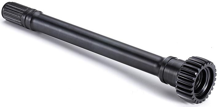
How do gear shafts differ from other components in gear mechanisms?
Gear shafts have distinct characteristics that differentiate them from other components in gear mechanisms. Here are some key differences between gear shafts and other components:
- Function:
Gear shafts serve as the mechanical linkages that connect and transmit rotational motion between gears. Their primary function is to transfer power and torque from one gear to another, enabling the desired mechanical output. Other components in gear mechanisms, such as gears themselves, may have different functions, such as meshing with other gears, providing different gear ratios, or changing the direction of motion.
- Structure and Design:
Gear shafts typically have a cylindrical or rod-like structure with a smooth surface. They are designed to provide support, alignment, and rotational movement for the connected gears. In contrast, other components, such as gears, may have complex tooth profiles, specific shapes, or specialized features to achieve their intended functions, such as transmitting motion, altering speed, or multiplying torque.
- Location and Mounting:
Gear shafts are often positioned centrally within gear mechanisms and are mounted on bearings or bushings. This central location allows them to connect with multiple gears and efficiently transmit power. Other components, such as gears, may be positioned at different locations within the mechanism, depending on their specific roles and interactions with other gears.
- Rotational Movement:
Gear shafts primarily rotate within the gear mechanism, transmitting the rotational motion from one gear to another. They are designed to withstand the torque and rotational forces applied during operation. In contrast, other components, such as gears, may have different types of movement or interactions, such as meshing with other gears, sliding, or engaging and disengaging with additional mechanisms or clutches.
- Size and Dimension:
Gear shafts can vary in size and dimension depending on the specific application and gear mechanism requirements. They need to be designed to handle the load, torque, and speed demands of the system. Other components, such as gears, may also come in various sizes, but their shape, tooth profiles, and dimensions are tailored to achieve specific gear ratios, rotational speeds, or torque multiplication.
- Material Selection:
Gear shafts are commonly made from strong and durable materials, such as steel or alloy metals, to withstand the forces and stresses encountered during operation. The material selection for gear shafts prioritizes strength, wear resistance, and fatigue resistance. Other components, such as gears, may have different material requirements based on their specific functions, such as hardness, friction properties, or heat dissipation.
In summary, gear shafts differ from other components in gear mechanisms in terms of their function, structure, location, movement, size, and material selection. Gear shafts primarily serve to transmit power and torque between gears, providing support, alignment, and rotational movement. Understanding these differences is crucial for designing and assembling efficient and reliable gear mechanisms.
editor by CX 2024-04-17
China Professional Hob Processing Gear Hobbing Machine Single Head Wet Cutting with Best Sales
Product Description
Δ The optimization of the design and qualified coatings allow the GOLP hobs to have a longer service life within higher cutting speed;
Δ GOLP hob is particularly suitable for dry cutting, high speed cutting and hardened cutting;
Δ We choose the material in the whole world, but they only will be selected after a rigorous evaluation of the quality of hard alloy and test;
Δ They play well in various processing environment;
Δ Experienced technical staff and full range of world class CNC machines and testing equipment give the hobs from GOLP very high precision and a stable quality. Our fast delivery, high quality, technical support and our after-sales service helps you to take the lead in your industry.
| Hob type | Involute gear hob, Rectangular spline hob, Cycloidal gear hob, Pulley hob, Worm hob, Involute spline hob, Straight side spline hob, Long worm roll, Special hob, Sprocket hob; |
| Accuracy Grade | A, AA or higher accuracy standard(AAA, AAAA), Issued by the KLINGELNBERG tool and ZOLLER tool testing center; |
| Hob materials | Hard alloy Powder, high-speed steel; |
| The processing environment | High speed cutting, Wet cutting, Dry cutting, Hardened cutting |
| The scope of application | Before grinding, Before shaving, Before shaving, Scraping, Roll finishing |
| Technical support | Processing method, Special gear hob design and manufacturing, Processing parameters, Special hob tooling design and manufacturing |
| The hobbing precision | Each of the GOLP hobs will be delivered after careful processing and strict detection; If the equipment is in good condition, the user can process GB6 grade, JIS2 grade or higher precision gear. |
| Diameter | Φ10-200mm |
| Length | 6-200mm |
| Modul | 0.1-8 |
| No.Of Starts | 1-7 |
| Bore Designs | Φ6-60mm |
| Shaft Designs | For all common machines and special housing |
| Warranty | 2 years |
HangZhou GOLP CNC MACHINERY CO.,Ltd is located in HangZhou–the core location of the HangZhouang CHINAMFG which is the most dynamic economy area in China. We are a new brand company specializing in the CNC machine tool industry. The company is mainly engaged in Die-casting machine, CNC Punching machines, Powder compacting machine and other new intelligent machine and related supporting products. The company adheres to the business philosophy –Professional quality, Credibility first, Customer first, and is committed to the development goal of becoming an important member of the global market in the field of intelligent machines.
Q:What’s your payment terms?
A:T/T,L/C,Paypal,Western Union etc.
Q:How long is the product warranty?
A: 24 months
Q: Are you a trading company or a manufacturer?
A: We are a professional manufacturer. Our products have been exported to Asia, South America, Africa, and have developed a good world wide reputation.
Q: What kind of product certification do you have?
A: All our products have passed ISO9001 and CE certifications. We have strict quality inspection process before leaving our factory in order to offer the best quality machines to our customers.
Q: Do you have after sales service?
A: Yes, we have special service team which will offer you professional guidance, or On-site installation in customer Factory.
Q: Do you test all your goods before delivery?
A: Yes, we have strict quality inspection process including a load test for every machine before leaving our factory.
/* January 22, 2571 19:08:37 */!function(){function s(e,r){var a,o={};try{e&&e.split(“,”).forEach(function(e,t){e&&(a=e.match(/(.*?):(.*)$/))&&1
| Standard: | Standard |
|---|---|
| Coating: | Coating |
| Worm: | Involute Worm |
| Head Number: | Multi-Head |
| Precision: | AA |
| Material: | High Speed Steel |
| Customization: |
Available
| Customized Request |
|---|
Can worm gears be used in precision manufacturing equipment?
Yes, worm gears can be used in precision manufacturing equipment. Here’s a detailed explanation of their use in precision manufacturing:
1. Precision Motion Control: Worm gears can provide precise motion control in manufacturing equipment. Their design allows for high gear ratios, which enables fine adjustments and precise positioning. This is particularly useful in applications where accurate and repeatable movement is required, such as CNC machines, robotic arms, and coordinate measuring machines (CMMs).
2. Load Holding and Backdriving Prevention: Worm gears have a self-locking characteristic, meaning they can hold loads in position without the need for additional brakes or clutches. This feature is advantageous in precision manufacturing equipment where holding a position is critical. The self-locking property also helps prevent backdriving, ensuring stability and accuracy during operation.
3. Compact Design: Worm gears have a compact design, which can be beneficial in space-constrained manufacturing equipment. Their worm and worm wheel configuration allows for a compact footprint, making them suitable for applications where size limitations exist.
4. High Torque Transmission: Worm gears can transmit high torque, making them suitable for heavy-duty precision manufacturing equipment. The meshing of the worm and worm wheel generates a large contact area, enabling efficient power transfer and load handling capabilities.
5. Reduced Noise and Vibration: Worm gears operate with a sliding motion rather than a rolling motion, resulting in reduced noise and vibration levels. This characteristic is advantageous in precision manufacturing equipment, as it helps maintain a quieter working environment and minimizes potential disturbances that could affect the precision of the manufacturing process.
6. Lubrication and Maintenance: Proper lubrication is crucial for the efficient and reliable operation of worm gears in precision manufacturing equipment. Lubricants help reduce friction and wear between the gear teeth, ensuring smooth and accurate motion. Regular maintenance and lubrication schedules should be followed to optimize gear performance and extend their service life.
While worm gears offer several advantages in precision manufacturing equipment, it’s important to consider the specific requirements of the application. Factors such as gear ratio, efficiency, backlash, and operating conditions should be carefully evaluated to ensure that worm gears are the appropriate choice for achieving the desired precision and performance.
Overall, worm gears can be successfully utilized in precision manufacturing equipment, providing precise motion control, load holding capabilities, compactness, and high torque transmission. When properly selected, installed, and maintained, worm gears can contribute to the accuracy, reliability, and efficiency of precision manufacturing processes.

How do you retrofit an existing mechanical system with a worm gear?
When retrofitting an existing mechanical system with a worm gear, several considerations need to be taken into account. Here’s a detailed explanation of the retrofitting process:
- Evaluate the existing system: Before proceeding with the retrofit, thoroughly assess the existing mechanical system. Understand its design, function, and limitations. Identify the specific reasons for considering a worm gear retrofit, such as the need for increased torque, improved efficiency, or enhanced precision.
- Analyze compatibility: Evaluate the compatibility of a worm gear with the existing system. Consider factors such as available space, structural integrity, alignment requirements, and the load-bearing capacity of the system. Ensure that the addition of a worm gear will not compromise the overall performance or safety of the system.
- Select the appropriate worm gear: Based on the requirements and constraints of the retrofit, choose a suitable worm gear. Consider factors such as gear ratio, torque capacity, efficiency, backlash, and mounting options. Select a worm gear that matches the specific needs of the retrofit and is compatible with the existing system.
- Modify or adapt the system: Depending on the compatibility analysis, it may be necessary to modify or adapt certain components of the existing system to accommodate the worm gear. This can involve making adjustments to shafts, bearings, housings, or other mechanical elements. Ensure that any modifications or adaptations are carried out with precision and adhere to industry standards.
- Install the worm gear: Install the selected worm gear into the modified or adapted system. Follow the manufacturer’s instructions and guidelines for proper installation. Pay attention to torque specifications, lubrication requirements, and any specific assembly procedures. Ensure that the worm gear is securely mounted and aligned to minimize misalignment and maximize performance.
- Test and optimize: After the installation, thoroughly test the retrofitted system to ensure its functionality and performance. Conduct tests to verify torque transmission, efficiency, backlash, noise levels, and any other relevant parameters. Monitor the system during operation and make any necessary adjustments or optimizations to fine-tune its performance.
- Document and maintain: Document the retrofitting process, including any modifications, adjustments, or optimizations made to the existing system. Keep records of installation procedures, test results, and maintenance activities. Regularly inspect and maintain the retrofitted system to ensure its continued performance and reliability.
It’s important to note that retrofitting an existing mechanical system with a worm gear requires expertise in mechanical engineering and an understanding of the specific system requirements. If you lack the necessary knowledge or experience, it is advisable to consult with professionals or engineers specializing in power transmission systems to ensure a successful retrofit.

How do you install a worm gear system?
Installing a worm gear system requires careful attention to ensure proper alignment, lubrication, and secure mounting. Here are the general steps involved in installing a worm gear system:
- Prepare the components: Before installation, ensure that all the components of the worm gear system, including the worm, worm wheel, bearings, and housing, are clean and free from any contaminants or damage. Inspect the components for any signs of wear or defects.
- Check alignment: Verify that the mating surfaces of the worm and worm wheel are clean and free from any debris. Ensure that the gear teeth mesh properly and that there is no excessive backlash or misalignment. Make any necessary adjustments or repairs before proceeding with the installation.
- Apply lubrication: Lubricate the worm gear system according to the manufacturer’s recommendations. Select a suitable lubricant that provides sufficient lubrication and reduces friction between the worm and worm wheel during operation. Apply the lubricant evenly to the gear teeth and other contact surfaces.
- Mounting: Position the worm gear system in the desired location, taking into account any space constraints or mounting requirements. Use appropriate fasteners, such as bolts or screws, to securely attach the system to the surrounding structure or base. Ensure that the mounting surfaces are clean, flat, and able to withstand the forces and loads exerted by the gear system.
- Alignment and adjustment: Once the worm gear system is mounted, check the alignment again and make any necessary adjustments. Ensure that the worm and worm wheel are properly engaged and that there is no excessive play or binding. Pay attention to any specified alignment tolerances provided by the manufacturer.
- Testing and operation: After installation, conduct a thorough functional test of the worm gear system. Verify that it operates smoothly, without unusual noise or vibration. Check for proper engagement of the gear teeth and ensure that the system performs as intended under different load conditions. Monitor the system’s performance during initial operation and address any issues or abnormalities promptly.
It’s important to follow the specific installation instructions provided by the gear system manufacturer. Different worm gear designs and applications may have additional installation requirements or considerations that should be taken into account.
Proper installation of a worm gear system ensures its reliable operation, minimizes wear, and maximizes its lifespan. If you are unsure about any aspect of the installation process, it is recommended to consult the manufacturer or seek the assistance of a qualified professional.
editor by CX 2024-04-17
China Professional Customized Large Gear Shaft for The Gearbox spurs gear
Product Description
Product Description
King Steel can supply you a variety of standard spline shafts to choose from, some applications require a custom spline shaft. Industry applications include construction, steel and mining.
Our Shafts
* Involute Spline Shafts
* Straight Sided Spline Shafts
* Metric Spline Shafts
Specification:
|
Product name |
Spline shaft |
||
|
Material |
Carbon steel,Alloy steel |
||
|
Structure |
Forging |
||
|
Process |
Lathing, milling,grinding,drilling |
||
|
Heat treatment |
mechanical property up to FB12007 after Quenching and tempering |
||
|
Max.diameter |
900mm |
||
|
Max.length |
4913mm |
||
|
Max.tolerance |
±0.2 |
||
|
Weight |
484kg |
We can customize spline shafts as per client’s specifications and requirements.
Manufacturing process:
Rraw matrial — Forging testing– Turning — Drilling — Heat Treatment — Milling– Grinding — Shaping and hobbing Process — Packing — Shipping.
After Sales Service
1. OEM and customized service.
2. Full machining, primer coating, surface treatment.
3. Complete material testing process.
4. Quality control
Contact us
Please contact us for more information and quotations.
/* January 22, 2571 19:08:37 */!function(){function s(e,r){var a,o={};try{e&&e.split(“,”).forEach(function(e,t){e&&(a=e.match(/(.*?):(.*)$/))&&1
| Material: | Alloy Steel |
|---|---|
| Load: | Drive Shaft |
| Stiffness & Flexibility: | Stiffness / Rigid Axle |
| Customization: |
Available
| Customized Request |
|---|
.shipping-cost-tm .tm-status-off{background: none;padding:0;color: #1470cc}
|
Shipping Cost:
Estimated freight per unit. |
about shipping cost and estimated delivery time. |
|---|
| Payment Method: |
|
|---|---|
|
Initial Payment Full Payment |
| Currency: | US$ |
|---|
| Return&refunds: | You can apply for a refund up to 30 days after receipt of the products. |
|---|
What are the safety considerations when working with gear shafts?
Working with gear shafts involves potential hazards that need to be considered to ensure the safety of individuals involved. Proper safety measures should be followed to prevent accidents and injuries. Let’s explore some important safety considerations when working with gear shafts:
- Personal Protective Equipment (PPE):
Wearing appropriate personal protective equipment is essential when working with gear shafts. This may include safety glasses or goggles to protect the eyes from flying debris, gloves to provide hand protection, and appropriate footwear to prevent foot injuries. PPE should be selected based on the specific hazards associated with the task.
- Machine Guarding:
Ensure that gear shafts and related machinery are properly guarded. Machine guards help prevent accidental contact with moving parts and reduce the risk of entanglement or entrapment. Guards should be in place and functioning correctly before any work is performed on or near gear shafts.
- Lockout/Tagout Procedures:
Prior to working on gear shafts, it is important to follow lockout/tagout procedures. These procedures involve isolating the machinery from its power source and ensuring that it cannot be energized accidentally. Lockout/tagout procedures help protect workers from unexpected startup or release of stored energy, minimizing the risk of injury.
- Proper Training and Knowledge:
Workers should receive proper training on the safe operation and maintenance of gear shafts. They should be familiar with the potential hazards, safety procedures, and emergency protocols. Training should cover topics such as safe handling, proper use of tools, and awareness of potential risks associated with gear shafts.
- Risk Assessment:
Conduct a thorough risk assessment before performing any work involving gear shafts. Identify potential hazards, assess the associated risks, and implement appropriate control measures. This may include evaluating the stability of the work area, assessing the need for additional support or lifting equipment, and identifying any potential pinch points or crush hazards.
- Proper Lifting Techniques:
When handling or moving gear shafts, use proper lifting techniques to prevent strain or injury. Avoid lifting heavy loads manually when possible and use mechanical lifting aids or equipment when necessary. Ensure that lifting equipment is in good working condition, properly rated for the load, and operated by trained personnel.
- Clean and Organized Work Area:
Maintain a clean and organized work area around gear shafts. Remove any unnecessary items or debris that could pose a tripping or slipping hazard. Keep tools and equipment properly stored when not in use to prevent accidents and injuries.
- Regular Maintenance and Inspection:
Perform regular maintenance and inspection of gear shafts to ensure their safe operation. Check for signs of wear, damage, or misalignment. Address any issues promptly and follow manufacturer’s guidelines for maintenance intervals and procedures. Regular inspections help identify potential safety concerns and prevent equipment failure.
- Communication and Collaboration:
Encourage effective communication and collaboration among team members when working with gear shafts. Clear communication ensures that everyone is aware of their roles and responsibilities and can alert others to potential hazards or unsafe conditions. Collaboration promotes a safety culture and allows for the sharing of knowledge and best practices.
By considering these safety measures when working with gear shafts, the risk of accidents and injuries can be significantly reduced. It is important to prioritize safety and create a work environment where individuals are informed, trained, and equipped to work safely with gear shafts.
How do gear shafts affect the overall operation and efficiency of gear systems?
Gear shafts play a crucial role in determining the overall operation and efficiency of gear systems within mechanical applications. They impact various aspects of gear system performance. Let’s explore how gear shafts affect the overall operation and efficiency:
- Power Transmission:
Gear shafts are responsible for transmitting power between gears in a gear system. The design and construction of the gear shaft directly influence the efficiency of power transmission. Proper alignment, accurate dimensions, and precise machining of the gear shaft ensure smooth rotation and optimal meshing of gear teeth. This reduces power losses due to friction, misalignment, or inefficient engagement, resulting in improved power transmission efficiency.
- Load Carrying Capacity:
Gear shafts bear the load and torque generated within a gear system. Their structural integrity and material properties determine the load carrying capacity of the gear system. A well-designed and robust gear shaft can withstand high loads without deformation or failure. By effectively distributing the load across the gear arrangement, gear shafts enhance the overall efficiency of the system and prevent premature wear or damage to the gears.
- Alignment and Gear Meshing:
Gear shafts ensure proper alignment and gear meshing within the gear system. Accurate machining and precise tolerances of the gear shaft facilitate the correct positioning of gears, ensuring optimal contact and engagement between gear teeth. Improper alignment or misalignment due to a faulty gear shaft can result in increased friction, noise, vibration, and reduced efficiency. Conversely, a well-designed gear shaft promotes smooth gear meshing, minimizes energy losses, and enhances the overall efficiency of the gear system.
- Reduction of Backlash:
Backlash refers to the slight play or gap between the meshing gear teeth. Gear shafts, when properly designed and manufactured, help reduce backlash within the gear system. By ensuring accurate alignment and precise tooth engagement, gear shafts minimize the amount of backlash, which can cause vibration, noise, and energy losses. Reduced backlash improves the efficiency of the gear system by enhancing the transfer of rotational motion and minimizing power dissipation.
- Smooth Operation and Reduced Wear:
A well-designed gear shaft enables smooth operation and reduces wear within the gear system. The accurate meshing of gear teeth facilitated by the gear shaft results in reduced friction and wear on the gears. Proper lubrication and the use of high-quality materials further contribute to minimizing wear and extending the lifespan of the gear system components. Smooth operation and reduced wear translate to improved efficiency, as energy losses due to friction and component degradation are minimized.
- Efficiency in Speed and Torque Conversion:
Gear shafts allow for efficient speed and torque conversion within gear systems. By incorporating different gear arrangements on a single gear shaft, it becomes possible to achieve specific speed and torque requirements. The gear ratios and sizes chosen for the gear arrangement on the gear shaft determine the conversion efficiency. Well-designed gear shafts enable precise speed and torque transmission, resulting in efficient power utilization and optimized performance of the gear system.
In summary, gear shafts significantly impact the overall operation and efficiency of gear systems. They influence power transmission efficiency, load carrying capacity, gear alignment and meshing, reduction of backlash, smooth operation and reduced wear, as well as speed and torque conversion efficiency. Proper design, construction, and maintenance of gear shafts are essential for maximizing the overall performance and efficiency of gear systems in mechanical applications.
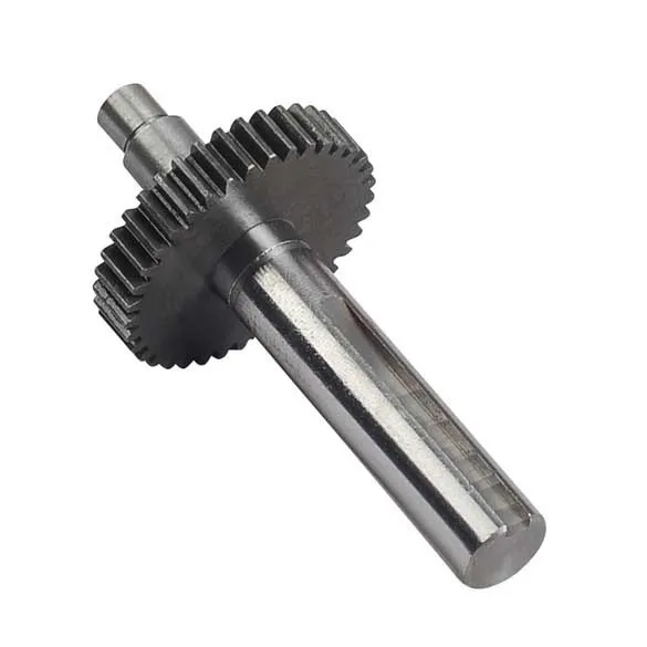
Can you describe the design and construction of a gear shaft?
The design and construction of a gear shaft are crucial factors in ensuring its functionality and durability within a mechanical system. A gear shaft is typically designed and constructed with specific considerations to meet the requirements of the application. Here’s a detailed description of the design and construction aspects of a gear shaft:
- Material Selection:
The choice of material for a gear shaft depends on various factors such as the application, operating conditions, and required strength. Common materials used for gear shafts include steel alloys, such as carbon steel, alloy steel, or stainless steel. These materials offer excellent strength, durability, and resistance to wear and fatigue. In some cases, gear shafts may also be made from other materials like brass or bronze for specific applications.
- Shape and Dimensions:
The shape and dimensions of a gear shaft are determined based on the specific requirements of the gear system and the mechanical system as a whole. Gear shafts are typically cylindrical in shape, with accurate dimensions and tolerances to ensure proper fit and alignment with the gears. The length and diameter of the gear shaft are determined based on factors such as the torque to be transmitted, the space available, and the required stiffness.
- Teeth and Splines:
In gear systems, gear shafts may have teeth or splines to provide a positive engagement with the gears. The teeth or splines are machined onto the gear shaft to ensure accurate meshing and transfer of rotational motion and torque. The shape, size, and profile of the teeth or splines depend on the specific gear system requirements, such as the module or pitch of the gears and the desired gear ratio.
- Bearing Surfaces:
Gear shafts often incorporate bearing surfaces to support and guide the rotation of the shaft within the mechanical system. These bearing surfaces can be in the form of journals or bushings, which reduce friction and wear. The design and construction of these bearing surfaces are critical to minimizing rotational resistance, ensuring smooth operation, and extending the lifespan of the gear shaft.
- Heat Treatment and Surface Finish:
To enhance the strength and durability of a gear shaft, heat treatment processes like quenching and tempering may be applied to improve the material’s properties. These processes can increase the hardness, toughness, and resistance to wear of the gear shaft. Additionally, the surface of the gear shaft may undergo finishing processes such as grinding, polishing, or coating to reduce surface roughness, enhance corrosion resistance, and improve overall performance.
- Accurate Machining and Tolerances:
The manufacturing of a gear shaft involves precise machining processes to achieve accurate dimensions and tolerances. CNC machining or other specialized machining techniques are employed to ensure the gear shaft’s proper fit and alignment with the gears and other components in the mechanical system. Tight tolerances are essential to achieve smooth and efficient operation, minimize backlash, and maintain the desired gear meshing characteristics.
In summary, the design and construction of a gear shaft involve material selection, consideration of shape and dimensions, implementation of teeth or splines, incorporation of bearing surfaces, application of heat treatment and surface finish, and accurate machining with tight tolerances. These design and construction aspects are crucial in creating a gear shaft that can efficiently transmit motion and power, withstand the operating conditions, and provide reliable performance within mechanical systems.
editor by CX 2024-04-16
China supplier Plastic Worm Gears and Worm Shaft for Telescope wholesaler
Product Description
Product Description
|
Products |
Gear |
|||
|
Module |
M0.3-M10 |
|||
|
Precision grade |
DIN5, DIN6, DIN7, DIN8, DIN10 |
|||
|
Pressure angle: |
14.5 degree, 15 degree, 20 degree |
|||
|
Material |
C45 steel, ,304SS, 316SS, 20CrMo,40Cr, brass, nylon, POM, and so on |
|||
|
Heat treatment |
Hardening and Tempering High Frequency Quenching Carburization etc |
|||
|
Surface treatment |
Blacking, Polishing, Anodization, Chrome Plating, Zinc Plating, Nickel Plating |
|||
|
Application |
Precision cutting machines.Lathes machine |
|||
|
Machining process: |
CNC engine latheCNC milling machine |
|||
Detailed Photos
Test
Inspection steps before delivery: Use GO/Nogo inspect hole—Use micrometer check dimensions—Next use stiffness detection system inspect hardness–Finally use CMM inspect precision
Packaging & Shipping
Company Profile
ZheJiang Haorongshengye Electrical Equipment Co., Ltd.
1. Was founded in 2008
2. Our Principle:
“Credibility Supremacy, and Customer First”
3. Our Promise:
“High quality products, and Excellent Service”
4. Our Value:
“Being Honesty, Doing the Best, and Long-lasting Development”
5. Our Aim:
“Develop to be a leader in the power transmission parts industry in the world”
|
6.Our services: |
1).Competitive price |
|||
|
2).High quality products |
||||
|
3).OEM service or can customized according to your drawings |
||||
|
4).Reply your inquiry in 24 hours |
||||
|
5).Professional technical team 24 hours online service |
||||
|
6).Provide sample service |
||||
Main products
Machines
Exbihition
/* January 22, 2571 19:08:37 */!function(){function s(e,r){var a,o={};try{e&&e.split(“,”).forEach(function(e,t){e&&(a=e.match(/(.*?):(.*)$/))&&1
| Application: | Machinery |
|---|---|
| Hardness: | Hardened Tooth Surface |
| Gear Position: | External Gear |
| Manufacturing Method: | Cut Gear |
| Toothed Portion Shape: | Spur Gear |
| Material: | Stainless Steel |
| Samples: |
US$ 100/Piece
1 Piece(Min.Order) | |
|---|
| Customization: |
Available
| Customized Request |
|---|
What lubrication is required for a worm gear?
The lubrication requirements for a worm gear system are crucial to ensure smooth operation, reduce friction, prevent wear, and extend the lifespan of the gears. The specific lubrication needed may vary depending on factors such as the application, operating conditions, gear materials, and manufacturer recommendations. Here are some key considerations regarding lubrication for a worm gear:
- Lubricant selection: Choose a lubricant specifically designed for gear applications, taking into account factors such as load, speed, temperature, and environment. Common lubricant types for worm gears include mineral oils, synthetic oils, and greases. Consult the gear manufacturer’s recommendations or industry standards to determine the appropriate lubricant type and viscosity grade.
- Viscosity: The lubricant viscosity is critical for effective lubrication. The viscosity should be selected based on the operating conditions and gear design parameters. Higher loads and slower speeds typically require higher viscosity lubricants to ensure sufficient film thickness and protection. Conversely, lower viscosity lubricants may be suitable for lighter loads and higher speeds to minimize power losses.
- Lubrication method: The lubrication method can vary depending on the gear system design. Some worm gears have oil sumps or reservoirs that allow for oil bath lubrication, where the gears are partially submerged in a lubricant pool. Other systems may require periodic oil application or greasing. Follow the gear manufacturer’s guidelines for the appropriate lubrication method, frequency, and quantity.
- Temperature considerations: Worm gear systems may encounter a wide range of temperatures during operation. Ensure that the selected lubricant can withstand the anticipated temperature extremes without significant degradation or viscosity changes. Extreme temperatures may require specialized high-temperature or low-temperature lubricants to maintain proper lubrication performance.
- Maintenance and monitoring: Regular maintenance and monitoring of the lubrication are essential for optimal gear performance. Periodically inspect the lubricant condition, including its cleanliness, viscosity, and contamination levels. Monitor operating temperatures and perform oil analysis if necessary. Replace the lubricant at recommended intervals or if signs of degradation or contamination are observed.
It’s important to note that the lubrication requirements may vary for different worm gear applications, such as automotive, industrial machinery, or marine systems. Additionally, environmental factors such as dust, moisture, or chemical exposure should be considered when selecting a lubricant and establishing a lubrication maintenance plan.
Always refer to the gear manufacturer’s recommendations and guidelines for the specific lubrication requirements of your worm gear system. Adhering to proper lubrication practices helps ensure smooth and reliable operation, minimizes wear, and maximizes the gear system’s longevity.
How do you ensure proper alignment when connecting a worm gear?
Ensuring proper alignment when connecting a worm gear is crucial for the smooth and efficient operation of the gear system. Here’s a detailed explanation of the steps involved in achieving proper alignment:
- Pre-alignment preparation: Before connecting the worm gear, it is essential to prepare the components for alignment. This includes cleaning the mating surfaces of the gear and shaft, removing any debris or contaminants, and inspecting for any signs of damage or wear that could affect the alignment process.
- Measurement and analysis: Accurate measurement and analysis of the gear and shaft alignment are essential for achieving proper alignment. This typically involves using precision alignment tools such as dial indicators, laser alignment systems, or optical alignment instruments. These tools help measure the relative positions and angles of the gear and shaft and identify any misalignment.
- Adjustment of mounting surfaces: Based on the measurement results, adjustments may be required to align the mounting surfaces of the gear and shaft. This can involve shimming or machining the mounting surfaces to achieve the desired alignment. Care should be taken to ensure that the adjustments are made evenly and symmetrically to maintain the integrity of the gear system.
- Alignment correction: Once the mounting surfaces are prepared, the gear and shaft can be connected. During this process, it is important to carefully align the gear and shaft to minimize misalignment. This can be done by observing the alignment readings and making incremental adjustments as necessary. The specific adjustment method may vary depending on the type of coupling used to connect the gear and shaft (e.g., keyway, spline, or flange coupling).
- Verification and final adjustment: After connecting the gear and shaft, it is crucial to verify the alignment once again. This involves re-measuring the alignment using the alignment tools to ensure that the desired alignment specifications have been achieved. If any deviations are detected, final adjustments can be made to fine-tune the alignment until the desired readings are obtained.
- Secure fastening: Once the proper alignment is achieved, the gear and shaft should be securely fastened using appropriate fasteners and tightening procedures. It is important to follow the manufacturer’s recommendations for torque values and tightening sequences to ensure proper clamping force and prevent any loosening or slippage.
It is worth noting that the alignment process may vary depending on the specific gear system, coupling type, and alignment tools available. Additionally, it is important to refer to the manufacturer’s guidelines and specifications for the particular gear and coupling being used, as they may provide specific instructions or requirements for alignment.
Proper alignment should not be considered a one-time task but an ongoing maintenance practice. Regular inspections and realignment checks should be performed periodically or whenever there are indications of misalignment, such as abnormal noise, vibration, or accelerated wear. By ensuring proper alignment during the initial connection and maintaining it throughout the gear’s operational life, the gear system can operate optimally, minimize wear, and extend its service life.
Are there different types of worm gears available?
Yes, there are different types of worm gears available to suit various applications and requirements. Here are some of the commonly used types:
Single Enveloping Worm Gear:
The single enveloping worm gear, also known as a cylindrical worm gear, has cylindrical teeth on the worm wheel that mesh with the helical thread of the worm. The teeth of the worm wheel wrap around the worm in a single enveloping manner. This design provides better contact and load distribution, resulting in higher load-carrying capacity and smoother operation. Single enveloping worm gears are commonly used in heavy-duty applications where high torque transmission is required.
Double Enveloping Worm Gear:
The double enveloping worm gear is a specialized type of worm gear that provides even greater load-carrying capacity compared to the single enveloping design. In a double enveloping worm gear, both the worm and the worm wheel have curved tooth profiles. The teeth of the worm wrap around the worm wheel while the teeth of the worm wheel wrap around the worm. This double enveloping action increases the contact area, improves load distribution, and enhances the gear’s efficiency. Double enveloping worm gears are used in applications that demand high torque and precision, such as aerospace and defense industries.
Non-enveloping Worm Gear:
The non-enveloping worm gear, also known as a non-throated worm gear, has a worm wheel with teeth that do not fully wrap around the worm. Instead, the worm wheel has straight or slightly curved teeth that engage with the helical thread of the worm. Non-enveloping worm gears are simpler in design and less expensive to manufacture compared to enveloping worm gears. They are commonly used in applications with moderate loads and where cost is a consideration.
Self-locking Worm Gear:
Self-locking worm gears are designed with a specific helix angle of the worm’s thread to provide a self-locking effect. This means that when the worm is not actively driving the worm wheel, the worm wheel is prevented from rotating backward and can hold its position securely. Self-locking worm gears find applications in systems where holding position or preventing backdriving is crucial, such as elevators, lifts, and certain industrial machinery.
These are just a few examples of the different types of worm gears available. The choice of worm gear type depends on factors such as the application requirements, load capacity, efficiency, and cost considerations.
editor by CX 2024-04-16