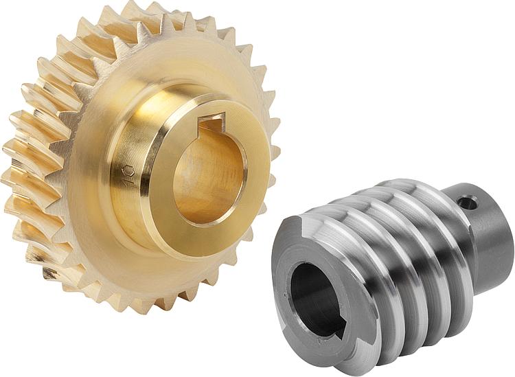
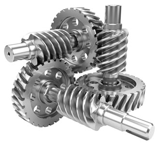
Product Description
DAECHANG TEC Product Description :
| Material | Carbon Steel | SAE1571, SAE1045, Cr12, 40Cr, Y15Pb, 1214Letc | |
| Alloy Steel | 20CrMnTi, 16MnCr5, 20CrMnMo, 41CrMo, 17CrNiMo5etc | ||
| Brass/Bronze | HPb59-1, H70, CuZn39Pb2, CuZn40Pb2, C38000, CuZn40etc | ||
| Type | OEM ODM Non-Standard Small Module Bevel Gears | ||
| Treatment | Heat treatments, Carburizing, Polishing | ||
| Standard | ISO /R 606 | ||
| Machining process | fabrication,stamping,deep drawing,gear hobbing, gear milling, gear shaping, machining and assembly gear broaching, gear grinding and gear gaping | ||
| Module | 1.0, 1.25, 1.5, 1.75, 2.0, 2.25, 2.5….8.0 etc | ||
| Tolerance control | Outer Diameter:±0.005mm | Length Dimension:±0.05 mm | |
| Teeth accuracy | GB1244-85, DIN8188, ISO/R 606 , ANSI B 29.1M | ||
| Heat treatment | Quenching & Tempering, Carburizing & Quenching, High-frequency Hardening, Carbonitriding… | ||
| Surface treatment | Blacking, Polishing, Anodization, Chrome plating, Zinc plating, Nickel plating… | ||
OUR FACTORY
OUR WORKSHOP
We can provide with sample for quality and function testing.
OUR MACHINE
| FAQ: | |
| Main Markets | North America, South America, Eastern Europe , West Europe , North Europe, South Europe, Asia |
| How to order? | * You send us drawing or sample |
| * We carry through project assessment | |
| * We give you our design for your confirmation | |
| * We make the sample and send it to you after you confirmed our design | |
| * You confirm the sample then place an order and pay us 30% deposit | |
| * We start producing | |
| * When the goods is done, you pay us the balance after you confirmed pictures or tracking numbers. |
| Packaging and Delivery time: | |
| Packaging | Polyethylene bag or oil paper for each item; |
| Pile on carton or as customer’s demand | |
| Delivery of Samples | By DHL, Fedex, UPS, TNT, EMS |
| Lead time | 10-15 working days as usual, 30days in busy season, it will based on the detailed order quantity. |
| Application: | Motor, Electric Cars, Motorcycle, Machinery, Marine, Agricultural Machinery, Car |
|---|---|
| Hardness: | Hardened |
| Manufacturing Method: | Cast/Cut/Rolling/Sintered Gear |
| Toothed Portion Shape: | Spur/Bevel/Curved/Doublehlical Gear |
| Material: | Stainless Steel |
| Type: | Circular/Wormand Worm Wheel/Bevel/Non-Circular/Rac |
| Samples: |
US$ 10/Piece
1 Piece(Min.Order) | |
|---|
| Customization: |
Available
| Customized Request |
|---|

Are worm gears suitable for high-torque applications?
Worm gears are indeed well-suited for high-torque applications. Here’s a detailed explanation of why worm gears are suitable for high-torque applications:
Worm gears are known for their ability to provide significant speed reduction and torque multiplication. They consist of a threaded cylindrical gear, called the worm, and a toothed wheel, called the worm wheel or worm gear. The interaction between the worm and the worm wheel enables the transmission of motion and torque.
Here are the reasons why worm gears are suitable for high-torque applications:
- High gear reduction ratio: Worm gears offer high gear reduction ratios, typically ranging from 20:1 to 300:1 or even higher. The large reduction ratio allows for a significant decrease in rotational speed while multiplying the torque output. This makes worm gears effective in applications that require high levels of torque.
- Self-locking capability: Worm gears possess a unique self-locking property, which means they can hold position and prevent backdriving without the need for additional braking mechanisms. The angle of the worm thread creates a mechanical advantage that resists reverse rotation of the worm wheel, providing excellent self-locking characteristics. This self-locking capability makes worm gears ideal for applications where holding the load in place is crucial, such as in lifting and hoisting equipment.
- Sturdy and robust design: Worm gears are typically constructed with durable materials, such as steel or bronze, which offer high strength and resistance to wear. This robust design enables them to handle heavy loads and transmit substantial torque without compromising their performance or longevity.
- High shock-load resistance: Worm gears exhibit good resistance to shock loads, which are sudden or intermittent loads that exceed the normal operating conditions. The sliding contact between the worm and the worm wheel teeth allows for some degree of shock absorption, making worm gears suitable for applications that involve frequent or unexpected high-torque impacts.
- Compact and space-efficient: Worm gears have a compact design, making them space-efficient and suitable for applications where size is a constraint. The compactness of worm gears allows for easy integration into machinery and equipment, even when there are spatial limitations.
It’s important to consider that while worm gears excel in high-torque applications, they may not be suitable for high-speed applications. The sliding contact between the worm and the worm wheel generates friction, which can lead to heat generation and reduced efficiency at high speeds. Therefore, worm gears are typically preferred in low to moderate speed applications where high torque output is required.
When selecting a worm gear for a high-torque application, it’s important to consider the specific torque requirements, operating conditions, and any additional factors such as speed, efficiency, and positional stability. Proper sizing, lubrication, and maintenance are also crucial to ensure optimal performance and longevity in high-torque applications.

How do you ensure proper alignment when connecting a worm gear?
Ensuring proper alignment when connecting a worm gear is crucial for the smooth and efficient operation of the gear system. Here’s a detailed explanation of the steps involved in achieving proper alignment:
- Pre-alignment preparation: Before connecting the worm gear, it is essential to prepare the components for alignment. This includes cleaning the mating surfaces of the gear and shaft, removing any debris or contaminants, and inspecting for any signs of damage or wear that could affect the alignment process.
- Measurement and analysis: Accurate measurement and analysis of the gear and shaft alignment are essential for achieving proper alignment. This typically involves using precision alignment tools such as dial indicators, laser alignment systems, or optical alignment instruments. These tools help measure the relative positions and angles of the gear and shaft and identify any misalignment.
- Adjustment of mounting surfaces: Based on the measurement results, adjustments may be required to align the mounting surfaces of the gear and shaft. This can involve shimming or machining the mounting surfaces to achieve the desired alignment. Care should be taken to ensure that the adjustments are made evenly and symmetrically to maintain the integrity of the gear system.
- Alignment correction: Once the mounting surfaces are prepared, the gear and shaft can be connected. During this process, it is important to carefully align the gear and shaft to minimize misalignment. This can be done by observing the alignment readings and making incremental adjustments as necessary. The specific adjustment method may vary depending on the type of coupling used to connect the gear and shaft (e.g., keyway, spline, or flange coupling).
- Verification and final adjustment: After connecting the gear and shaft, it is crucial to verify the alignment once again. This involves re-measuring the alignment using the alignment tools to ensure that the desired alignment specifications have been achieved. If any deviations are detected, final adjustments can be made to fine-tune the alignment until the desired readings are obtained.
- Secure fastening: Once the proper alignment is achieved, the gear and shaft should be securely fastened using appropriate fasteners and tightening procedures. It is important to follow the manufacturer’s recommendations for torque values and tightening sequences to ensure proper clamping force and prevent any loosening or slippage.
It is worth noting that the alignment process may vary depending on the specific gear system, coupling type, and alignment tools available. Additionally, it is important to refer to the manufacturer’s guidelines and specifications for the particular gear and coupling being used, as they may provide specific instructions or requirements for alignment.
Proper alignment should not be considered a one-time task but an ongoing maintenance practice. Regular inspections and realignment checks should be performed periodically or whenever there are indications of misalignment, such as abnormal noise, vibration, or accelerated wear. By ensuring proper alignment during the initial connection and maintaining it throughout the gear’s operational life, the gear system can operate optimally, minimize wear, and extend its service life.

How do you choose the right size worm gear for your application?
Choosing the right size worm gear for your application involves considering several factors to ensure optimal performance and longevity. Here are the key considerations:
Load Requirements:
Determine the maximum load that the worm gear will need to transmit. This includes both the torque (rotational force) and the axial load (force along the axis of the gear). Calculate or estimate the peak and continuous loads that the gear will experience during operation. Consider factors such as shock loads, dynamic forces, and variations in load conditions. This information will help determine the required load-carrying capacity of the worm gear.
Gear Ratio:
Determine the desired gear ratio for your application. The gear ratio determines the speed reduction and torque multiplication provided by the worm gear system. Consider the specific requirements of your application, such as the desired output speed and the torque needed to drive the load. Select a worm gear with a gear ratio that meets your application’s requirements while considering the limitations of the available gear options.
Efficiency:
Consider the efficiency requirements of your application. Worm gears typically have lower efficiency compared to other types of gears due to the sliding action between the worm and worm wheel. If efficiency is critical for your application, choose a worm gear design and materials that offer higher efficiency, such as a double enveloping worm gear.
Space Constraints:
Evaluate the available space for the worm gear assembly in your application. Consider the dimensions of the worm gear, including the diameter, length, and mounting requirements. Ensure that the chosen worm gear can fit within the available space without compromising other components or functionality.
Speed and Operating Conditions:
Consider the operating speed and environmental conditions in which the worm gear will operate. Some worm gears have speed limitations due to factors such as heat generation and lubrication requirements. Ensure that the selected worm gear is suitable for the anticipated speed range and can withstand the temperature, humidity, and other environmental factors of your application.
Manufacturing Standards and Quality:
Select a worm gear that conforms to recognized manufacturing standards and quality requirements. Look for worm gears from reputable manufacturers that offer reliable and durable products. Consider factors such as material quality, surface finish, and precision in the gear manufacturing process.
By carefully evaluating these factors and considering the specific requirements of your application, you can choose the right size worm gear that meets your performance, load, and space requirements, resulting in a reliable and efficient gear system.


editor by CX 2023-09-16